MagnetometerDIY geomagnetic storm monitoring | |||||||||||||||||||||||||||||||||||||||||||||||||||||||||||||||||||||||||||||||||
| |||||||||||||||||||||||||||||||||||||||||||||||||||||||||||||||||||||||||||||||||
The schematics diagram of the sensor is shown below. It is just a voltage divider reacting to the differential lighting of the two photoresistors: 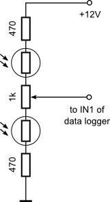 The 470-Ohm resistors are there as a protection for the times when the sensor is exposed to external light - in that case the resistance of both photosensors can become too low and the extra resistors help limit the current. The 1 kOhm potentiometer in the middle is for centering the signal - adjust it to ensure that when the laser spot is centered the output voltage is centered too (i.e. around 6V). Up to this point we've been looking only at the sensor itself - nothing was said about the way the signal is amplified, processed, and recorded. For amplifying and digitizing the signal I use a device that is another of my projects - the data logger described here. Just for completeness, here is the schematics of the data logger: 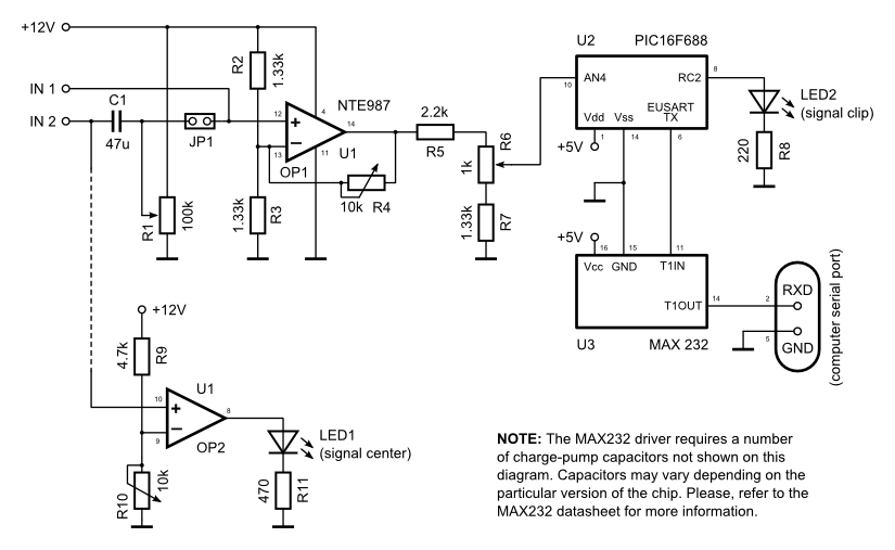 Full information about it including construction notes and data processing software is available in the Data Logger page. Check the next page for samples of data as well as near-real-time measurements of the magnetic field. |
|||||||||||||||||||||||||||||||||||||||||||||||||||||||||||||||||||||||||||||||||
| |||||||||||||||||||||||||||||||||||||||||||||||||||||||||||||||||||||||||||||||||