MagnetometerDIY geomagnetic storm monitoring | |||||||||||||||||||||||||||||||||||||||||||||||||||||||||||||||||||||||||||||||||
| |||||||||||||||||||||||||||||||||||||||||||||||||||||||||||||||||||||||||||||||||
I found several different magnetometer designs on Internet, but I tend to be very picky. None of those was what I needed - something that is sensitive enough to record the small magnetic field variations where I live (San Jose, California), robust enough to work for long periods of time without constant maintenance, and relatively easy to construct. Since the only place where I could permanently install the sensor away from disturbances is on the patio of our apartment, another important consideration was that it should not be influenced by major changes in temperature or humidity. My magnetometer is of a torsion design. Torsion magnetometers work as follows: A magnet, attached to a mirror, is suspended from a thread. A laser beam is reflected from the mirror and falls on a detector. Changes in the Earth's magnetic field turn the magnet and the attached mirror, twisting the torsion thread. The reflected beam changes its position on the sensor, the changes are recorded and plotted on a chart. 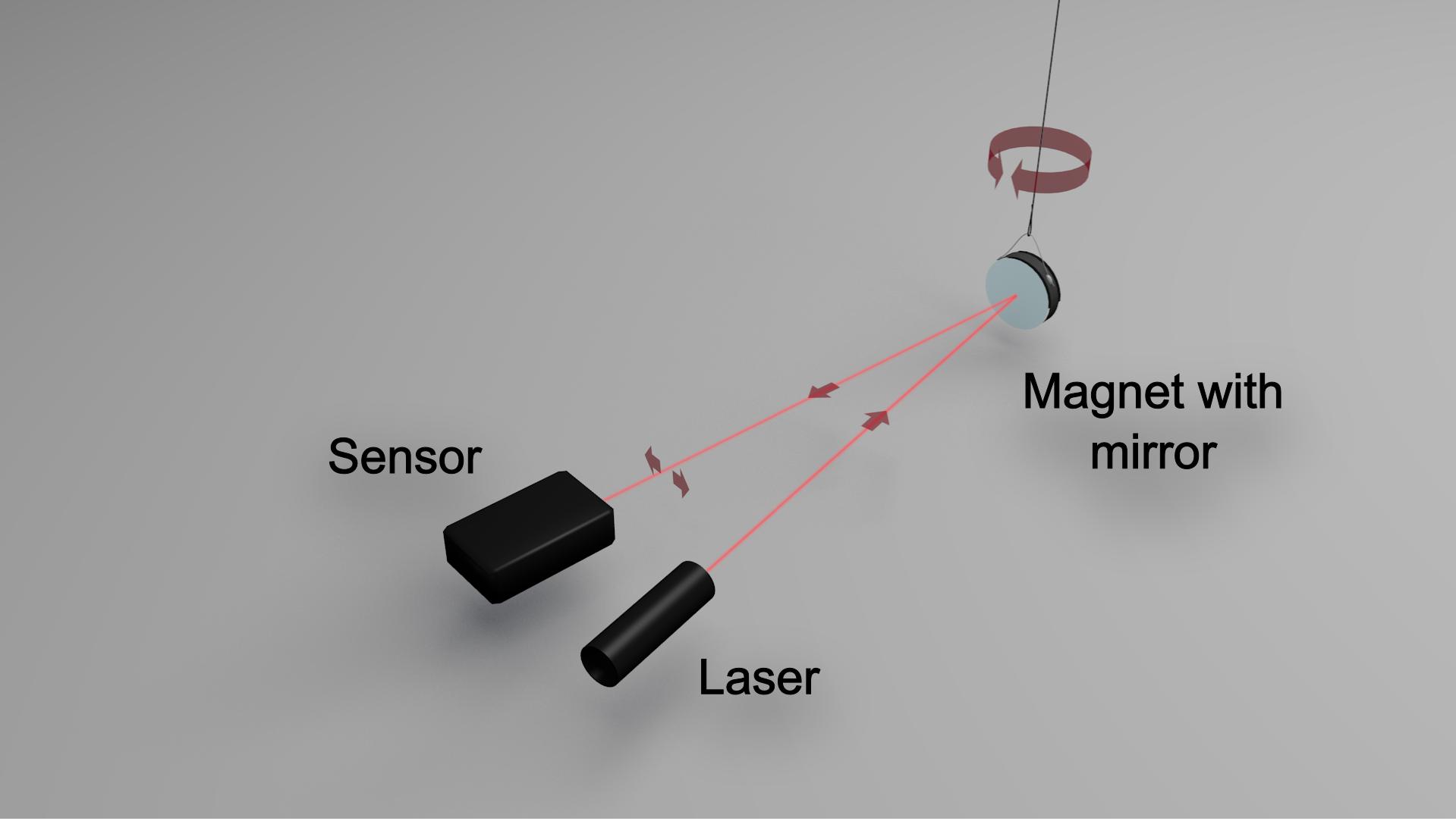 This sounds simple enough, but there are some precautions to be taken when designing such magnetometer. First, the changes of the magnetic field, at least at the latitude of California, are quite small. Sensitivity of the magnetometer can be easily improved to detect those small changes by increasing the distance between the mirror and the detector. High sensitivity, however, comes at a price - any slight disturbance (say, by an air current) will cause tiny movements of the mirror that are enough to completely mess up the data. The mirror must be protected from such disturbances. Magnetic disturbances abound too. A kid parking her bicycle nearby or a neighbor opening his refrigerator door is enough to set the mirror in motion. Once in motion, the mirror will keep oscillating for quite a while unless there is a way to dampen such oscillations. Finally, the position of the sensor relatively to the mirror must be stable too. A rock-solid mirror won't be of any use if the sensor moves this or that way with every slight vibration. I came up with the following design, constructed out of PVC pipe: 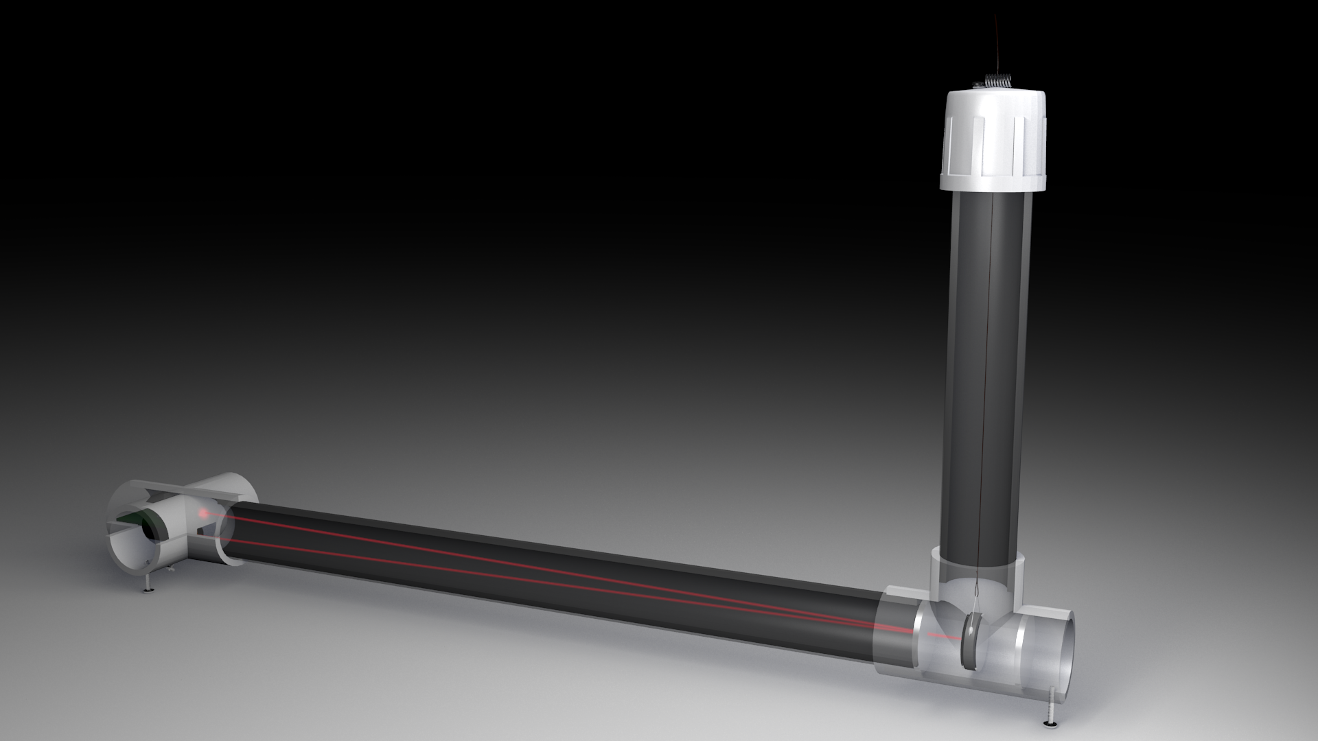 The mirror/magnet is hanging by the torsion thread in the vertical tube on the right. Two transparent plexiglass windows close the sides of the T at the bottom. This allows the lower part of the assembly to be filled with water or oil (I'm currently using plain tap water - works well enough for now) to quickly dampen any random movements of the mirror.  The laser and the sensor are located in the cross-joint on the left. The laser is held down by a spring and is sitting on four screws that can be adjusted to precisely point the laser, as shown on the first image below: 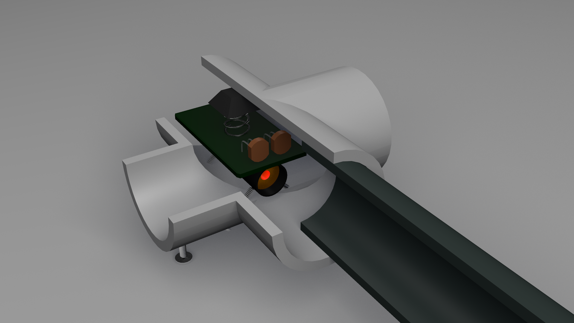 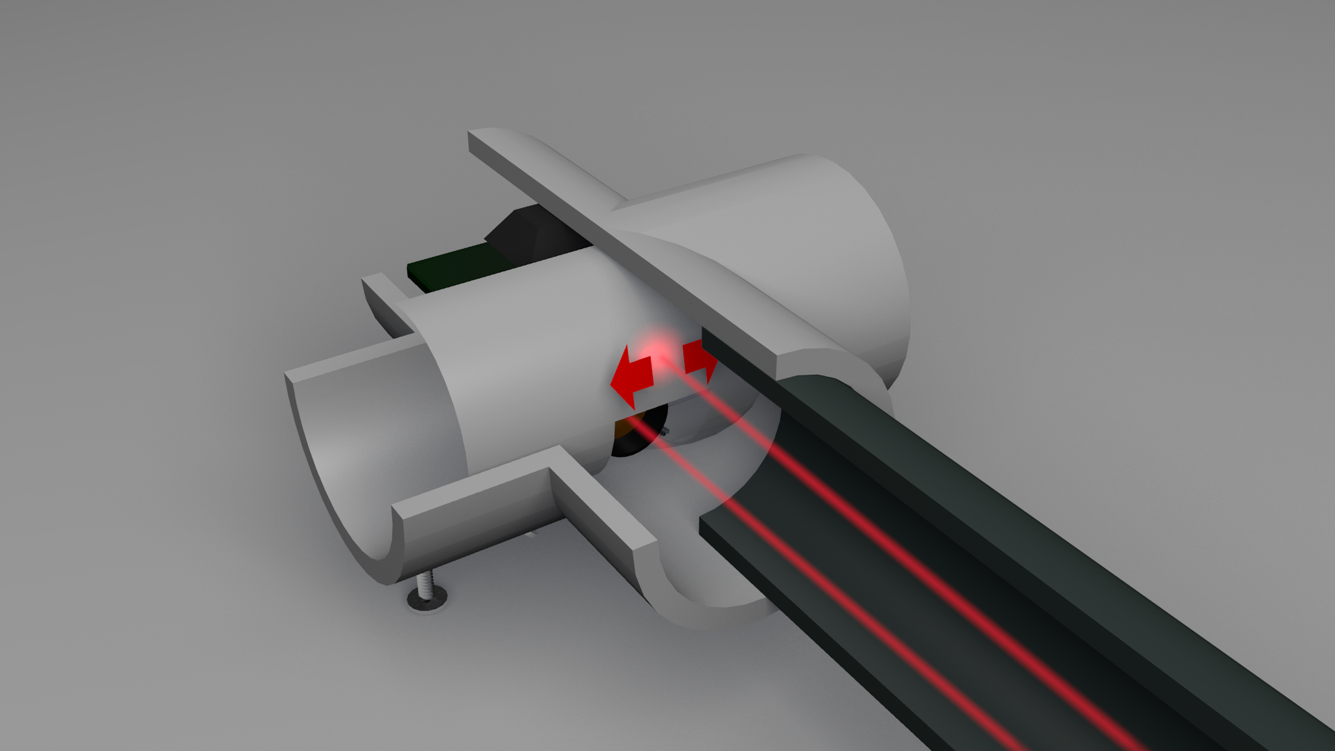 The light bounces back from the mirror and reaches a semi-transparent screen (second image). Behind the screen there are two photo-resistor cells forming a voltage divider. The relative illumination of each photo-resistor cell depends on the position of the reflected light spot. This way the output voltage from the divider smoothly follows the movements of the mirror. Check the animation below to see how the different parts of the magnetometer fit together: [ Download in HD, AVI/4.8MB ] So much for the plans. The following pages describe the actual construction of the magnetometer. |
|||||||||||||||||||||||||||||||||||||||||||||||||||||||||||||||||||||||||||||||||
| |||||||||||||||||||||||||||||||||||||||||||||||||||||||||||||||||||||||||||||||||