3D Printed Modular RC Rover
For as long as I can remember, one of my dreams has been to design and build my own remote-controlled car. This was one of the things that got me into electronics as a kid. I grew up and never got to building my own until - almost by accident - I got a 3D printer as a gift...
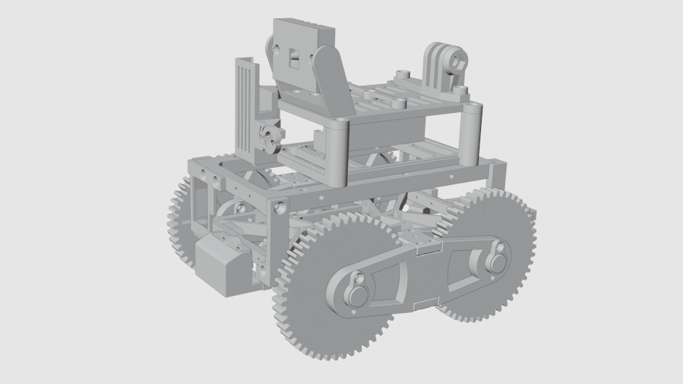
The result is this small 3D-printed remote-controlled rover. The design may not be elegant (I'm still learning the tricks of mechanical design) but is modular and easy to tinker with. You can use only the wheel frames and build your own chassis, replace the control box with something else, add or remove attachments such as FPV camera, GoPro holder, design your own tank tracks, etc.
The modularity makes the rover easy to repair too. For example, if the friction bearings need replacement, you can only print and replace the small bearing jackets instead of the whole wheel frame.

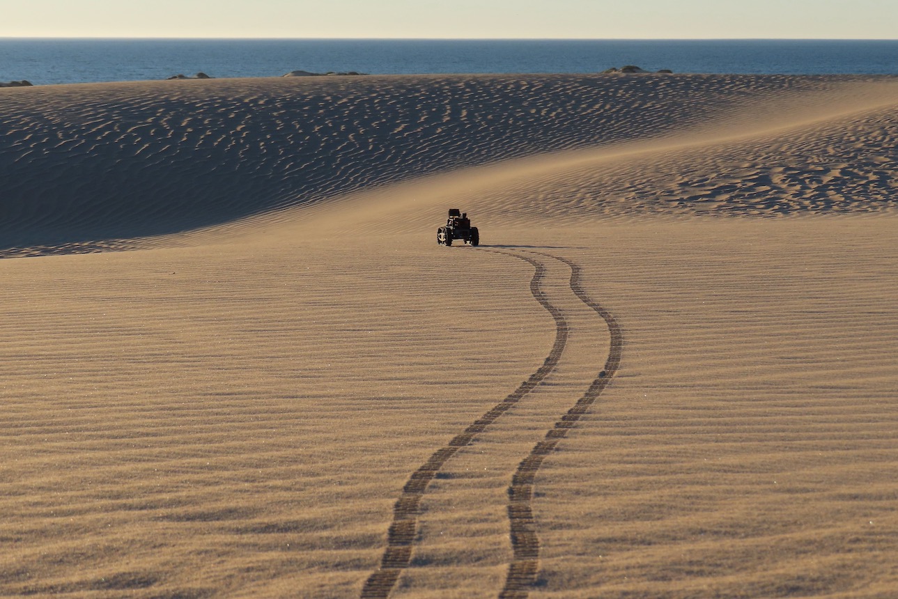
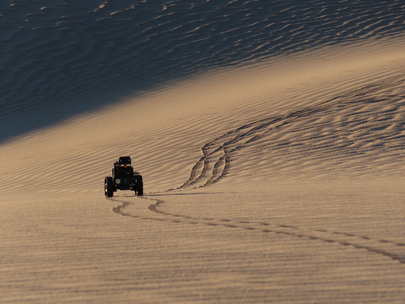
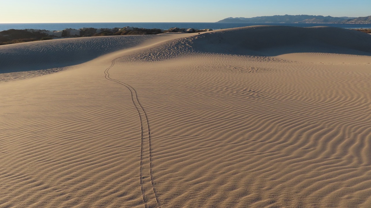
The rover is not intended for racing - with the motors I used it is rolling around at a slow deliberate pace. But this was the goal - with FPV goggles, even exploring the backyard turns into an adventure. You can change the motors, if you wish, and make it faster - just beware that you have to select motors that are powerful enough to provide enough torque.
The following videos will show you what you can expect with the "default" motors I used:
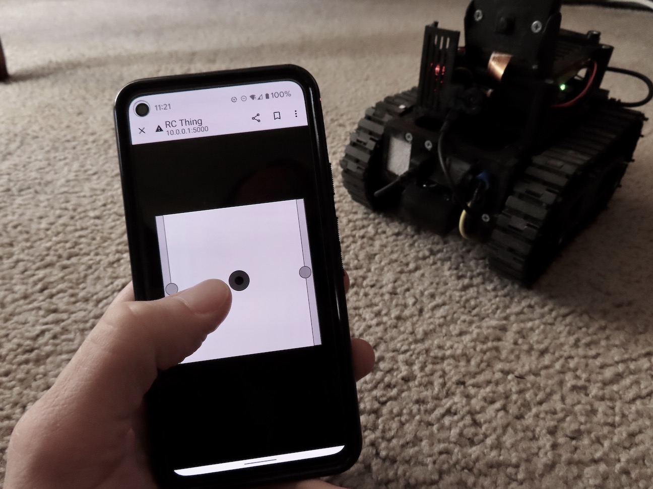
The rover is controlled over WiFi by a Raspberry Pi Zero 2 W. You can control it from your phone or from a computer, with or without joystick.
This project assumes you are able to wire up the motors, the motor controller, and the Raspberry Pi (or whatever else you decide to use) on your own. Some coding may also be needed, even if you decide to use the provided control software - you will need to adjust the GPIO pins in the code to match your wiring. In addition, configuring the Raspberry Pi - setting the network, is up to you. I recommend setting the network in a standalone hotspot mode - this way you can take the rover anywhere and control it from your phone. Alternatively, you may wish to have it connect to your home Wi-Fi - this way you'll be able to control it remotely over the internet.
What you need

STL files for the 3D printed parts. Click here to download. All parts can be printed without support (however, you may have to rotate the parts before printing them to ensure that). Check the details further down on this page on what you have to print and what is optional and how all pieces fit together. Also, the Image Gallery has photos of the various 3D printed parts.
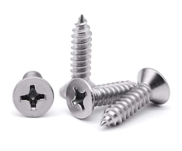
A bunch of #4 1/2 flat head wood screws. You'll need those to assemble the rover. A box with 100 screws should be plenty. Note that you may have to chop the tips of the screws when attaching certain parts to make sure they don't protrude too much. I found that diagonal cutting pliers work excellent. An alternative is to have a small box of shorter screws, if you can find some. In addition to the #4 screws, if you are using Raspberry Zero 2 W, you will need four M2.5 mounting screws or some small wood/plastic screws to mount it in the control box.
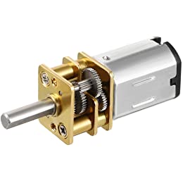
A pair of geared 12V mini RC motors. There are many variations of this type of motor. I'd recommend picking something that's in the 100-300 RPM range, since this provides a decent torque. You can go with higher RPMs, but then you have to make sure the motor you pick has enough power/torque.
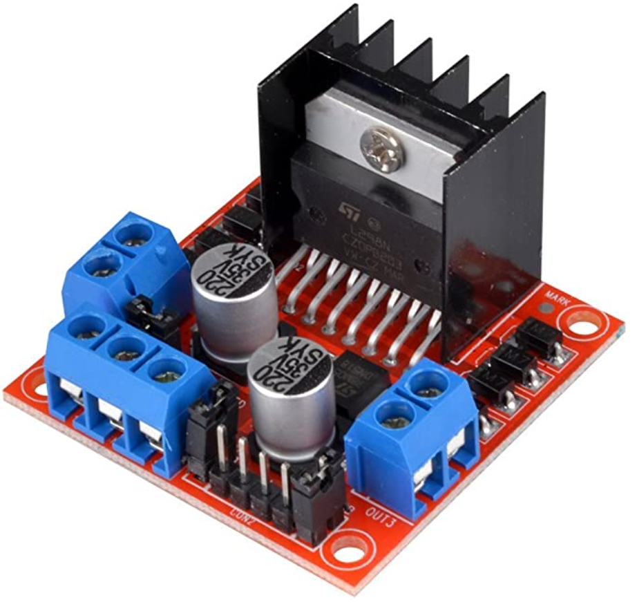
Motor controller. I used an L298N-based module, but you can use whatever you like. If you get something different, you may have to change the design of the motor controller holder.
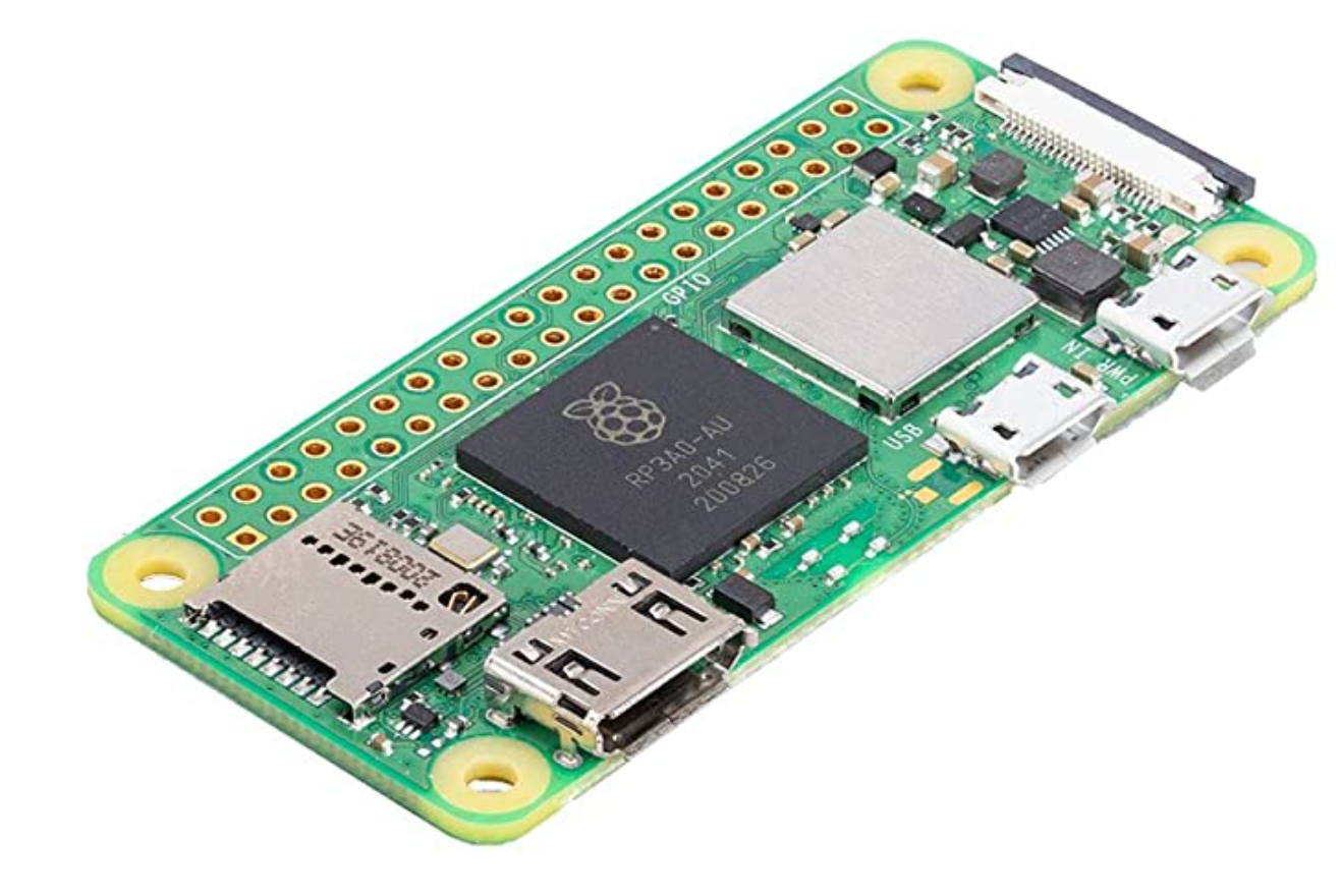
A Raspberry Pi or something equivalent. I have the Zero 2 W, but you can use whatever you are most comfortable with.
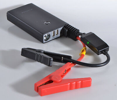
Power is provided by an AC55385 car jump starter battery pack. You can use any of the many available battery packs of the same size. The battery gives me hours of runtime on a single charge. If you use a different power pack, you have to change the chassis dimensions to make it fit.
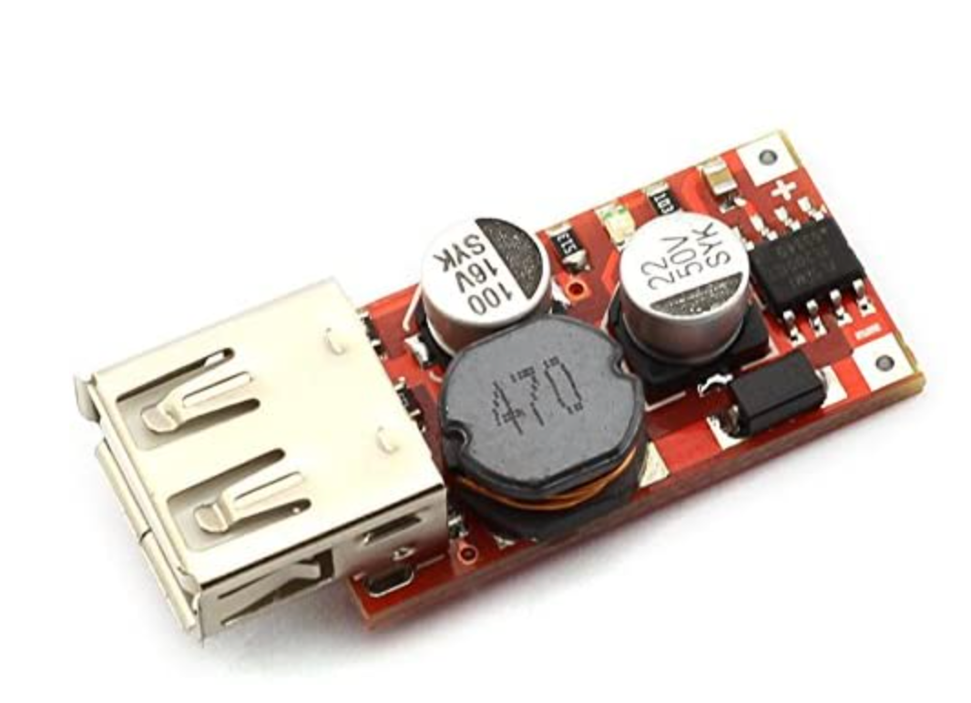
I found that the 5V USB output from my battery pack was unreliable and was causing the Raspberry Pi to hang and reboot randomly, so I used a 12V to 5V power regulator with 3A output. If your battery already has a reliable 5V output, you don't need this.
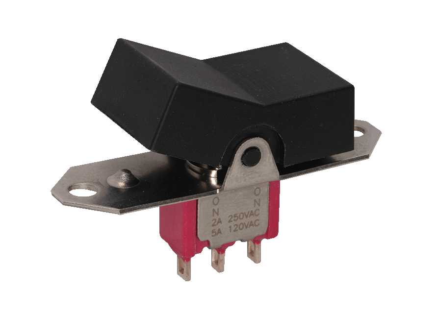
A power switch. The STL files include the design for a simple power switch holder and a safety cover for the switch (so the rover doesn't turn off if it bumps into something). You may have to change the design of those two components, depending on the power switch you happen to have.
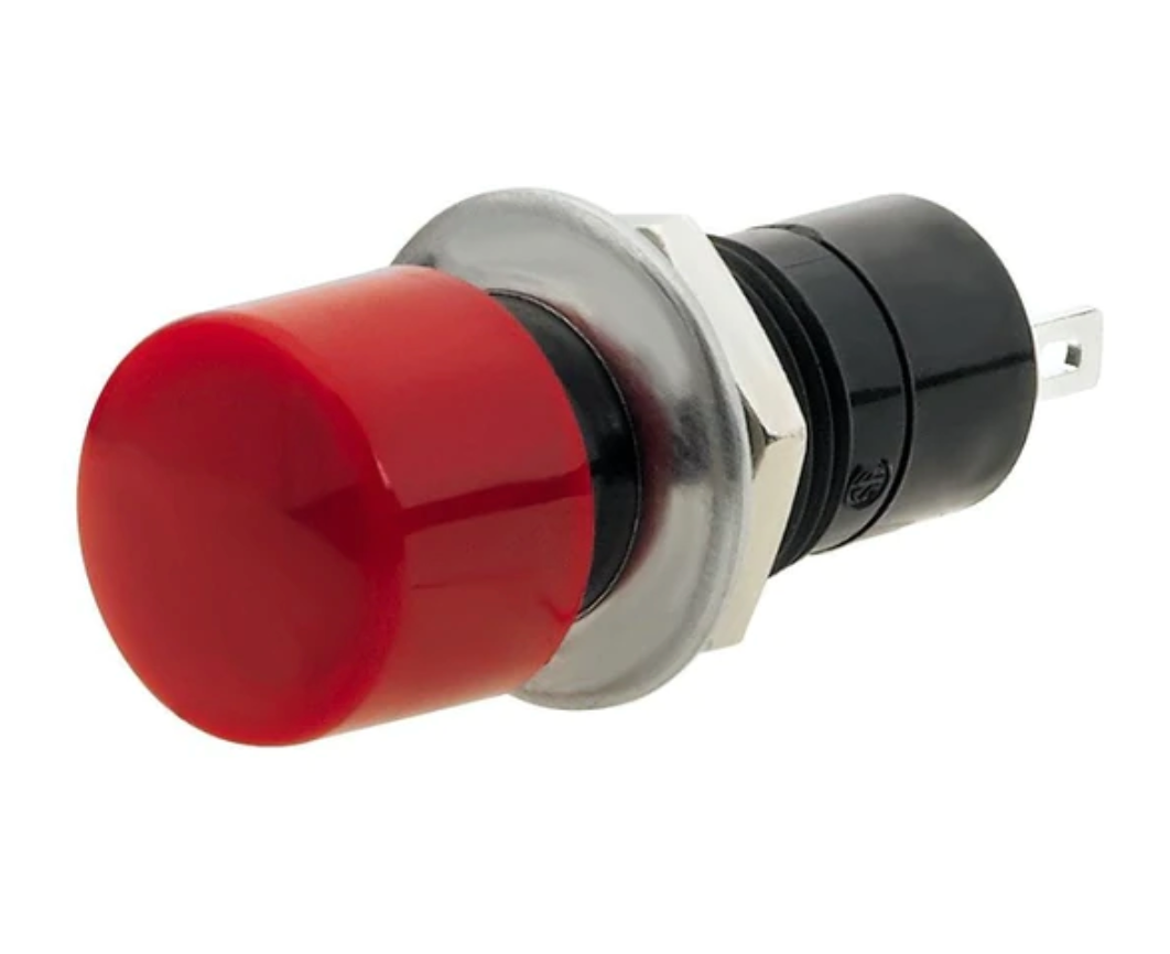
While you can power the rover off just by toggling the power switch, this is not a nice thing to do. I've included a push-button that is connected to two of the Raspberry Pi GPIO pins. The software (see next item) monitors those two pins. When you press and hold the switch for more than 5 seconds, the RPi will shut down. Then you can power it off.
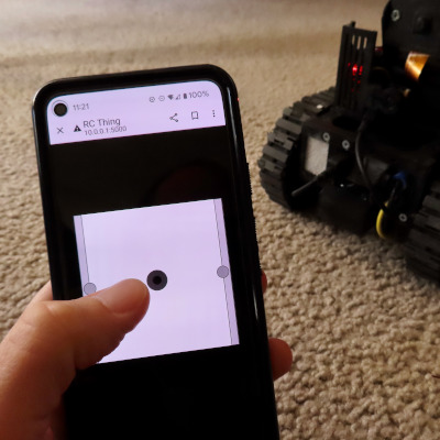
Control software. Click here to download. If you wish, you can use the code I've written for controlling the rover. It is a Python Flask server that lets you connect from a browser on port 5000 of the RPi. If you have a joystick, you can use this too. I even tried pairing a Nintendo Switch controller to my phone and the whole contraption just worked. Note that you may want to change the GPIO pin numbers in the code, depending on how you wire the rover.

An FPV camera with transmitter. Optional. If you already happen to have FPV goggles I highly recommend getting an FPV camera. Depending on the camera you get you might have to redesign the FPV camera/transmitter holder.
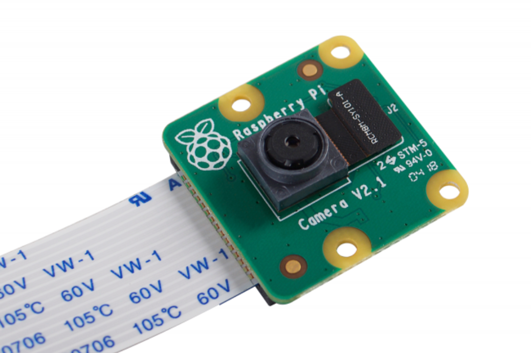
Raspberry Pi camera module. Optional. If you want to do something more (like, having a way to take high-resolution pictures from the rover, or try your hand at autonomous navigation), you can get one of those. The STL files include a tilting camera holder.
I recommend printing, assembling, nd testing the rover piece by piece. For example, try printing the wheels and the wheel frame, make sure this works and fits your motors, that you are satisfied with the speed and torque. Different 3D printers and printing materials may require slight adjustments and the earlier you find about any problems, the less time and materials you will waste. Once you have a component that works and fits the rest, continue with the next part.
You don't need all components to get a functional rover. For example, if you are going to be using the rover exclusively indoors, you don't really need the crawler tracks. The toothed wheels are perfectly suited for use on the floor and work even on thick carpet. Similarly, if you don't plan to add an FPV camera, you won't need the camera holder.
Below you will find description of the different components and the way they are assembled, in the order I would recommend printing them. If something is not clear, you can refer to the Image Gallery which has additional close-ups.
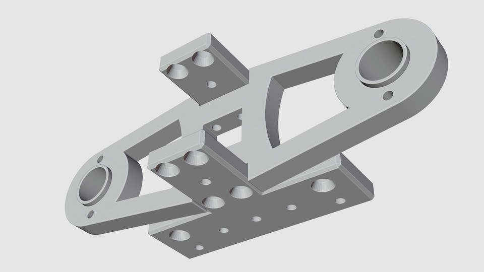
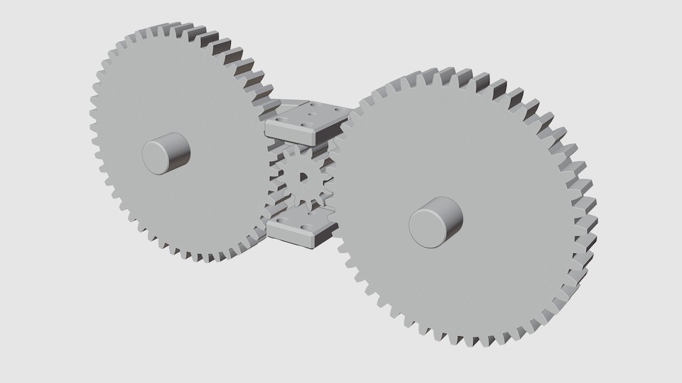
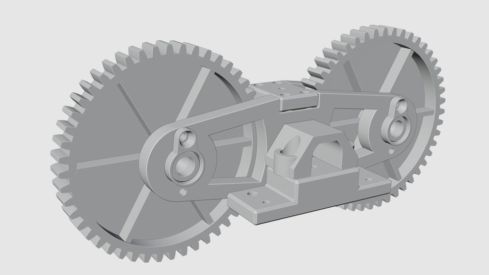
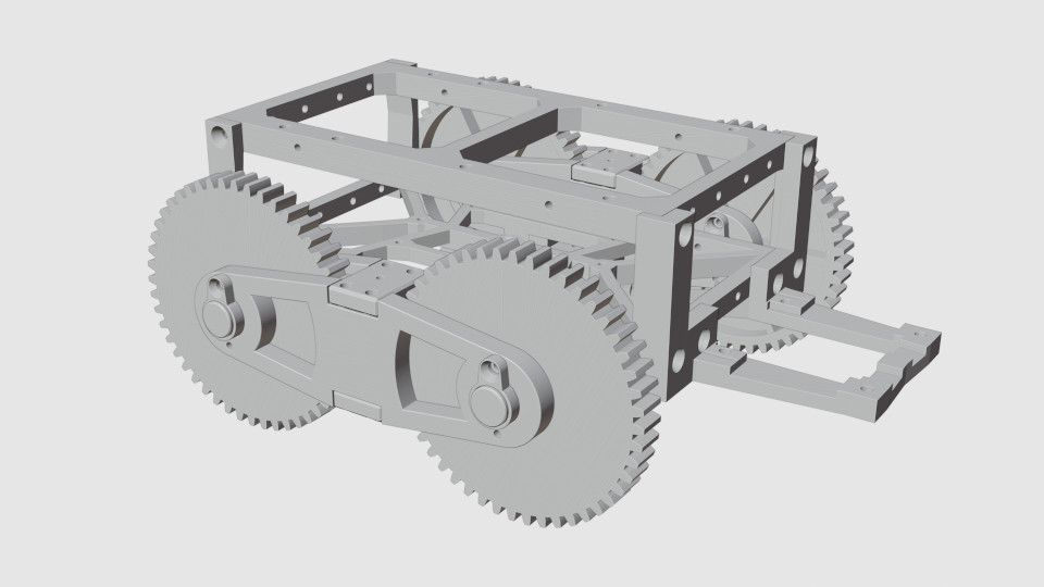
Wheel Frames
The rover drives around on two wheel frames. Each wheel frame consists of the following elements:
- an inner and outer frame, with a pair of bearing jackets each;
- upper and lower frame brackets;
- a single motor gear;
- two identical gear wheels, each with a separate axle peg and cap;
- a C-clamp that holds the motor attached to the lower bracket and protects the motor gears from dust/sand.
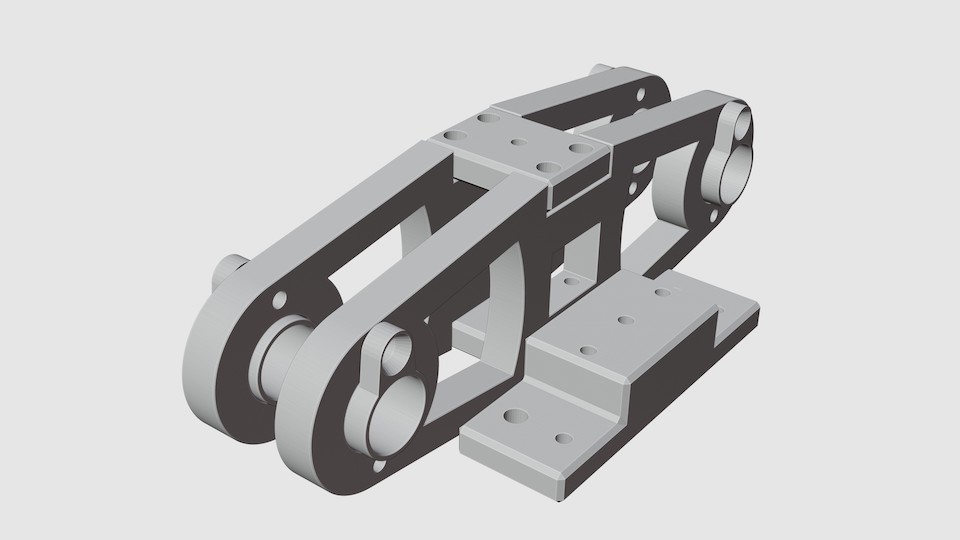
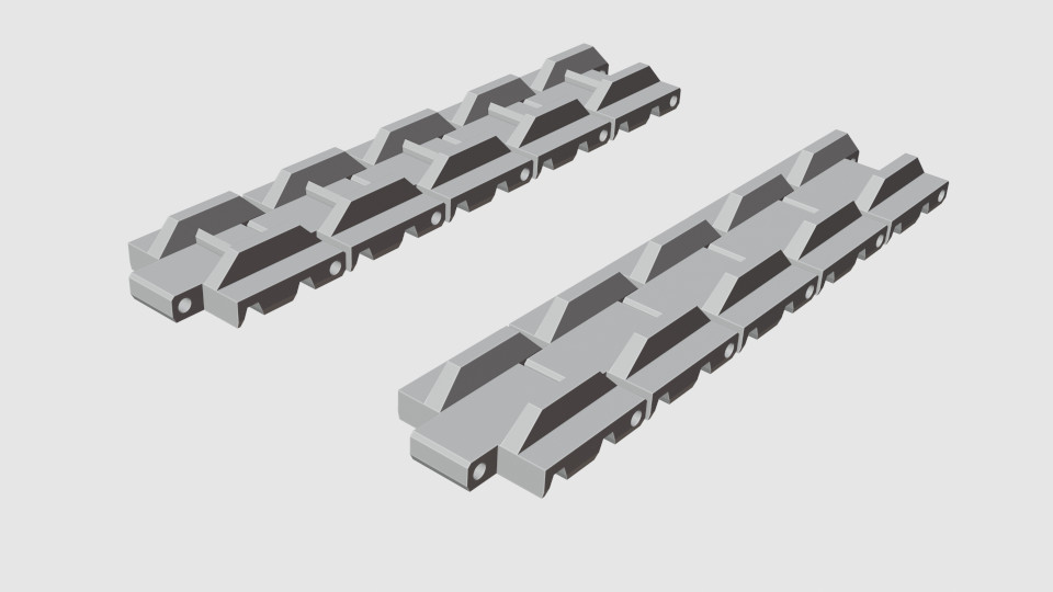
Tracks (optional)
While the rover can be used without tracks indoors, if you plan to take it outdoors you will need tracks to protect the wheel gears and to give it extra support on soft surfaces. There are two types of track link - smooth ones, and track links with a bar on the inner surface that grips the gear wheel teeth.
For each wheel frame you will need 21 links. I recommend using ~16 smooth links and ~5 links with inner bar. Attach the links with short pieces of printer filament, then pinch each piece on both sides with pliers, flattening the ends to keep it in place.
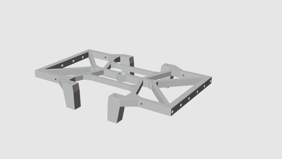
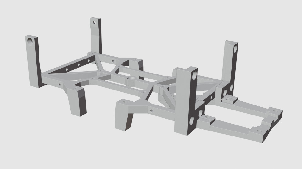
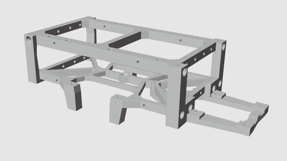
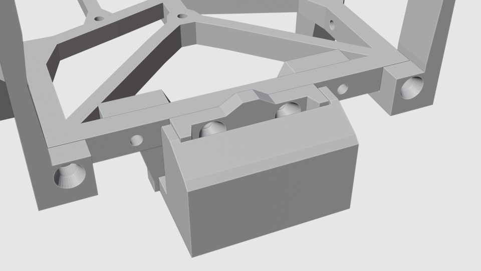
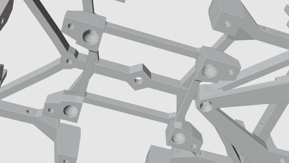
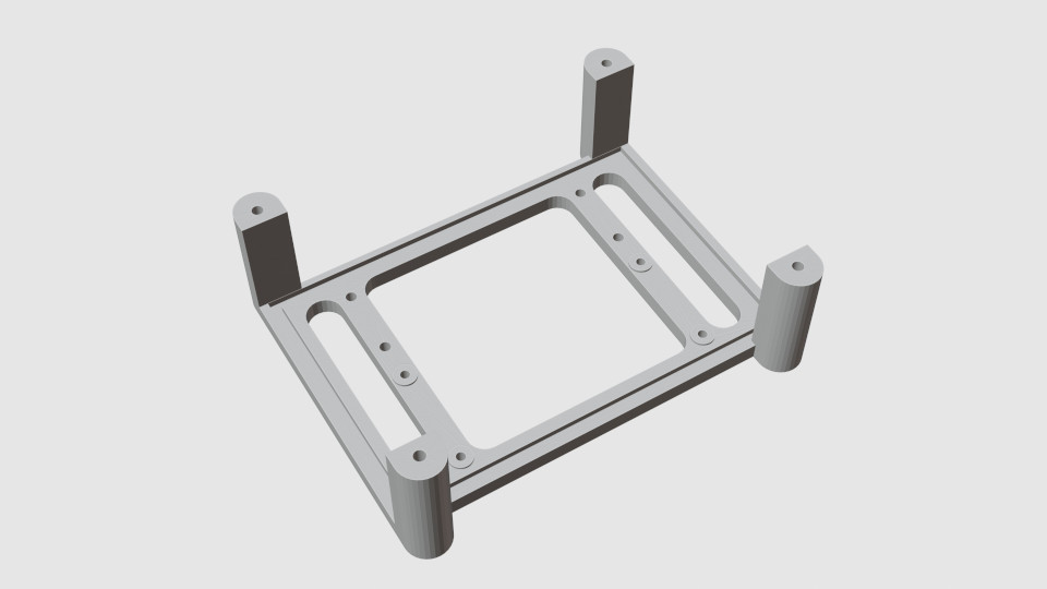
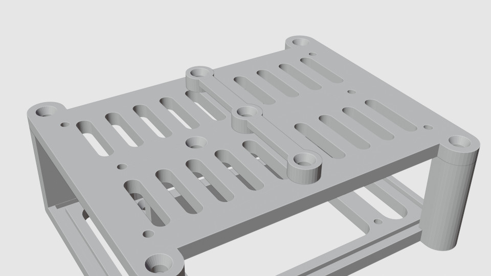
Chassis
The chassis attaches to the wheel frames and holds the battery in place. The chassis includes:
- a base (lower frame);
- two (left and right) front posts;
- rear posts and motor controller holder, all as a single part;
- a top frame.
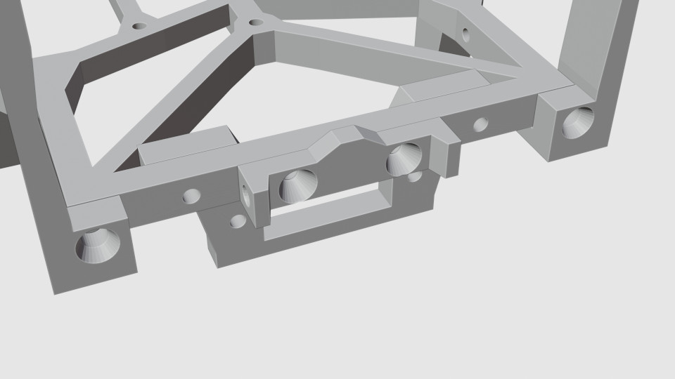
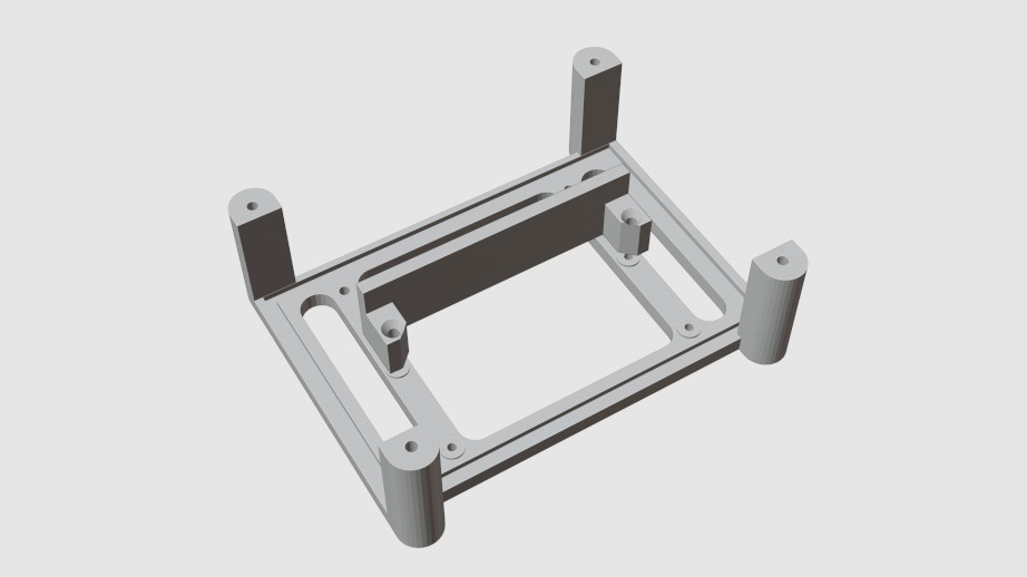
Chassis Electronics Attachments
The parts here will depend on how you will choose to wire your rover and what switch you will find. The design below fits my power switch and the PCB I used, but you may need to modify it to fit your requirements. The attachments include:
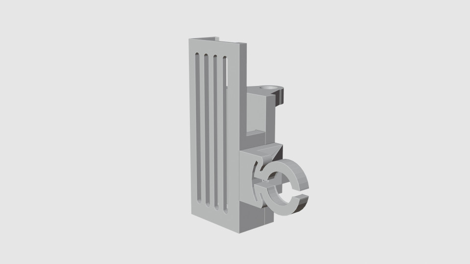
- a switch holder to hold the power switch;
- a cover holder for attaching the switch safety cover;
- a switch safety cover to prevent the rover from turning off it if bumps into something;
- two holder brackets to allow a prototype board to be attached under the belly of the crawler; the prototype board is used to wire the power switch, motors, and the RPI power module.
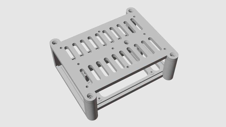
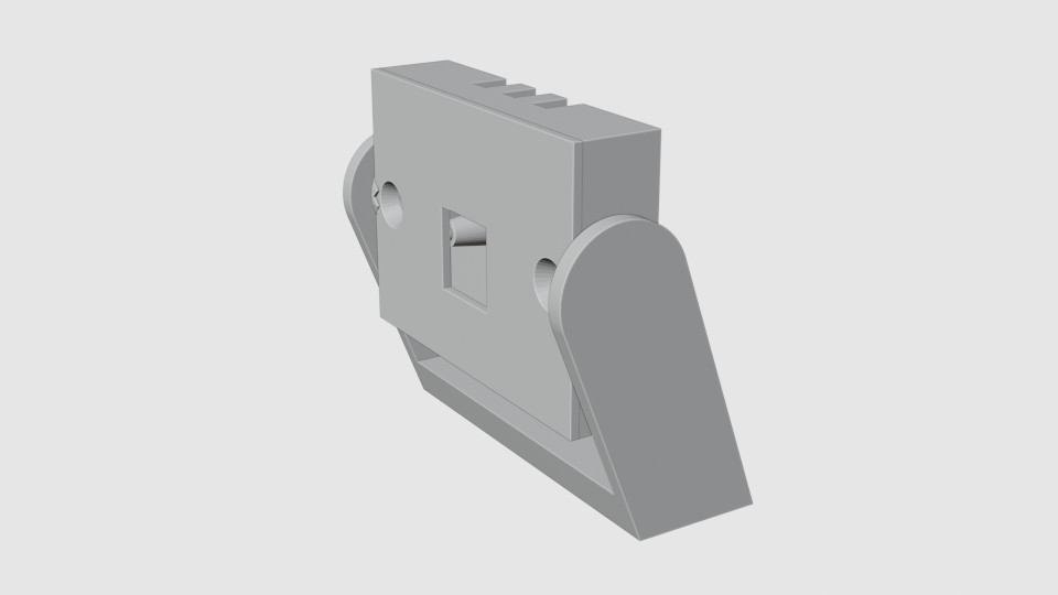
Control Box
I used a Raspberry Pi Zero 2 W to control the rover. If you are using a different controller, you may have to change the design of the control box. The current box is large enough to hold a standard-size Raspberry Pi too, but you may need to adjust the attachment points. The box I have consists of:
- a base, with attachment holes; this can be screwed to the top chassis frame;
- a top;
- an optional space separator that can be attached on one side of a RPI-zero, dividing the control box in two; this creates a small additional compartment to the side where you can organize the power cables;
- optional sides that slot in place; the sides that are provided as STL files fit Raspberry Pi 1B; a Pi Zero will not need those sides; in any case those are easy to modify if you need them, using the provided files as templates. One of the sides has a circular hole you can use to mount the shutdown button - you can use this or mount the button elsewhere.
Optional Attachments
Here are several optional parts you can use on your rover:
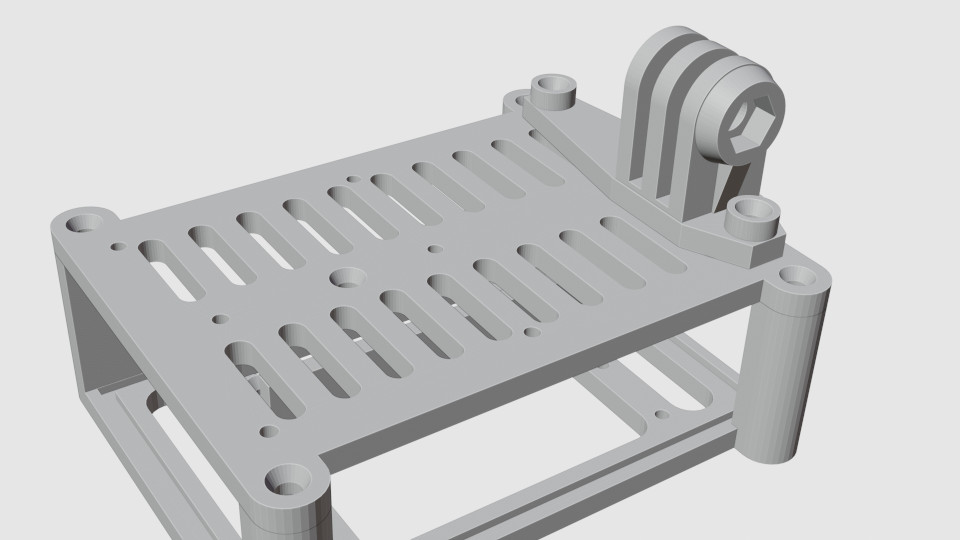
- FPV camera holder + transmitter holder;
- GoPro camera holder;
- swiveling holder for RPI camera module;
- cable organizer bar that can be mounted on top of the control box;
- light diffuser frame for smoother illumination, if you use a battery with built-in LED light.
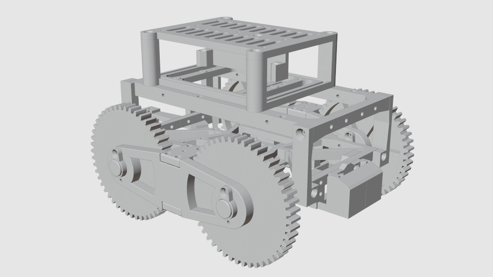
Here is how everything fits together:
If you decide to build this rover, and encounter any problems, please feel free to contact me at alex@avtanski.net. I'll appreciate your feedback, and also any photos or videos of your rover you'd like to share.

This work is licensed under a Creative Commons Attribution 4.0 International License.