| Countdown Timer | ||||||||||||
| Main | Pinout & Example | Code | Timer Applications | Other Projects | ||||||||
|
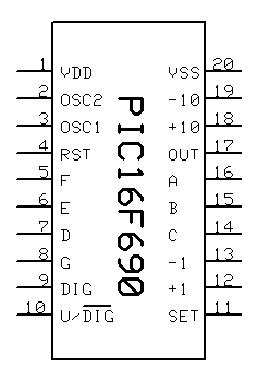
Programming your PIC 16F690 with the timer code will turn it into a convenient dedicated timer chip, ready to be incorporated in your projects. The diagram on the right shows the effective pin layout. You can find detailed description on each pin function below. Also, check the sample schematic diagram at the end of this page and the Sample Applications section. Pin Description
|
 |
Sample Application
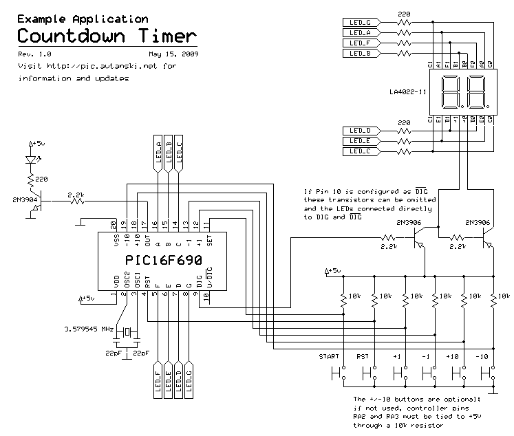
The following sample schematics uses the PIC16F690 timer to control a single LED (the one on the left, connected to the
OUT pin). If you don't want to customize pin 10 (see U / Inv.DIG above), you can configure it as Inv.DIG output and get rid of the two transistors and resistors used for digit selection. In that case, you can connect DIG directly to the digit 1 cathode (+1), and Inv.DIG to digit 2 cathode (+2).

Click on the schematics for higher resolution image.
PCB layout
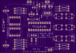
 | In the Timer Applications section you can find a link to PCB layout files by Eirik H. Snerthammer. Eirik, thanks for sharing! |
| Main | Pinout & Example | Code | Timer Applications | Other Projects | ||||||||
 | ||||||||||||