
| ||||||||||||||
| Main | Schematics & Code | Construction | Customize It! | Try It! | Other Projects | |||||||||
Initially I was planning to use the smallest possible box that could fit a 9V battery, a PIC microcontroller, a 16x2 LCD module and a switch. But then I found out that although a 16x2 character display works OK, a 20x4 display is way better and allows much longer excuses to be displayed without paging. This required a bigger box than the initial plans called for. Then came the idea to use some kind of fancy (and bigger) switch to turn the device on and off - so, another step up in the box size.
In the end, I decided to use something that is big enough for any future modifications, and I chose to sacrifice a Cardinal 14.4Kbps external fax modem - the same type I used and found very nice for another of my projects.
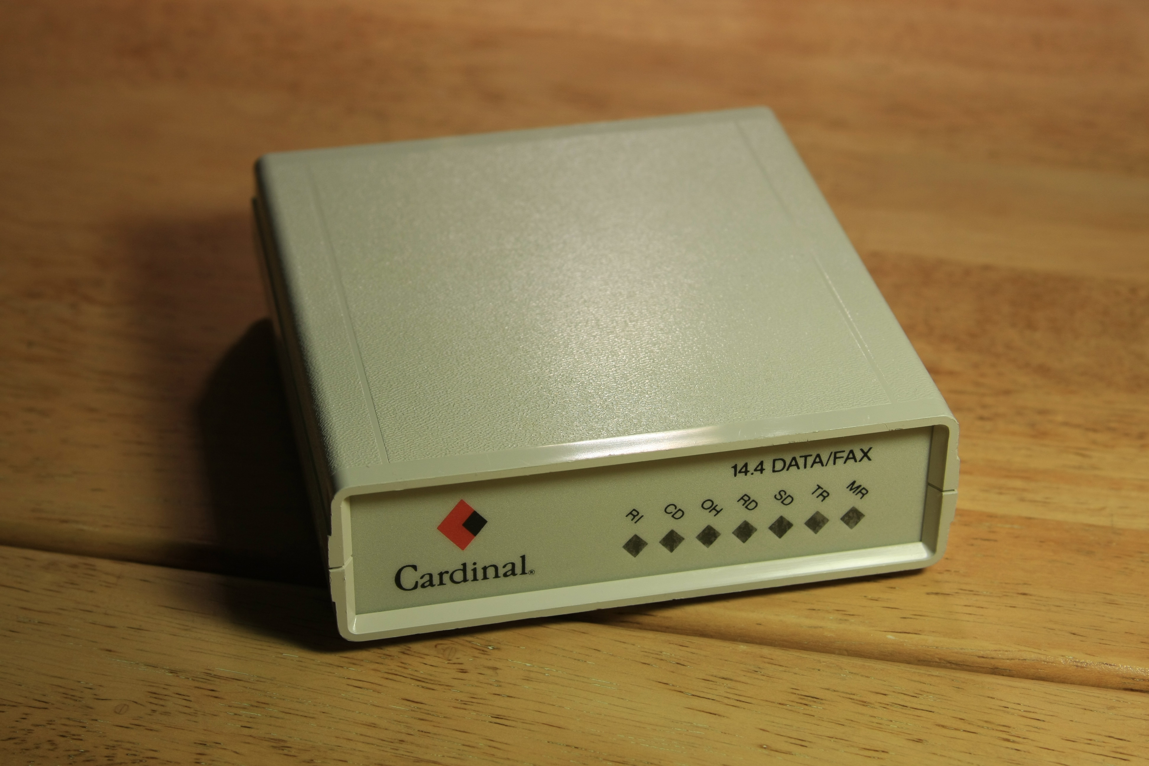
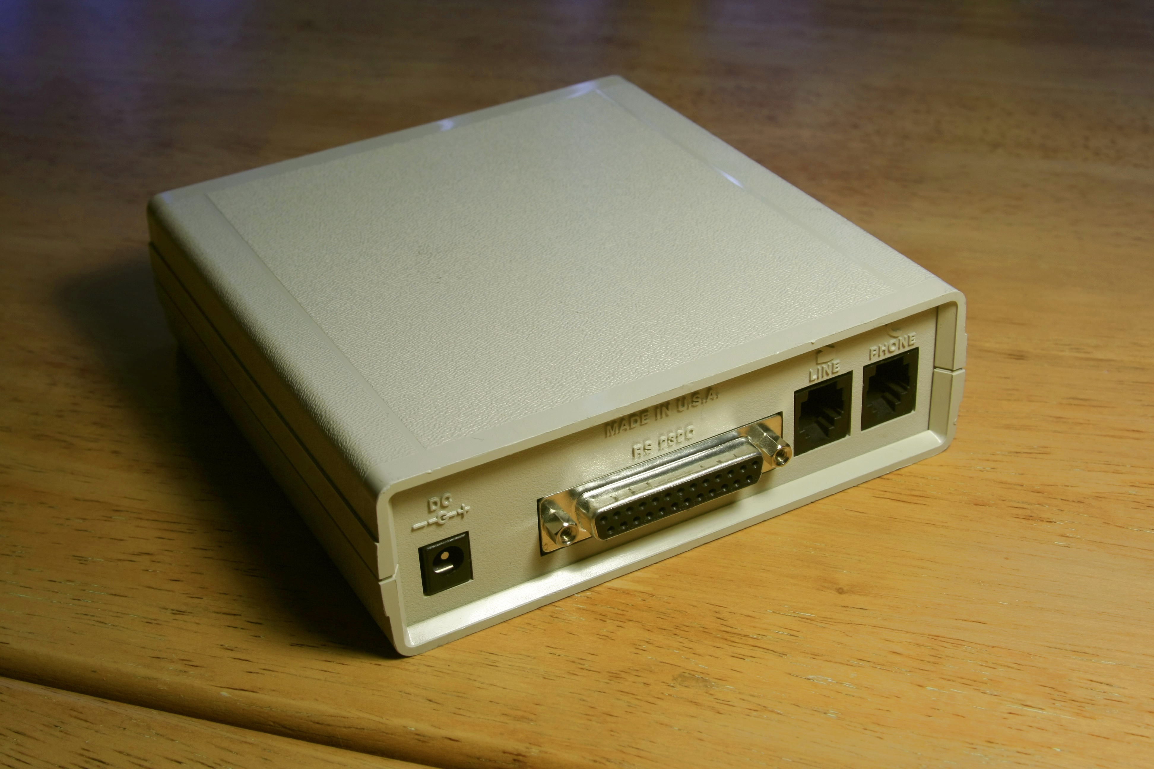
The parallel port at the back could be used to reprogram the microcontroller without having to open the box. The other ports could come handy too for future extensions or for plugging an external power supply.
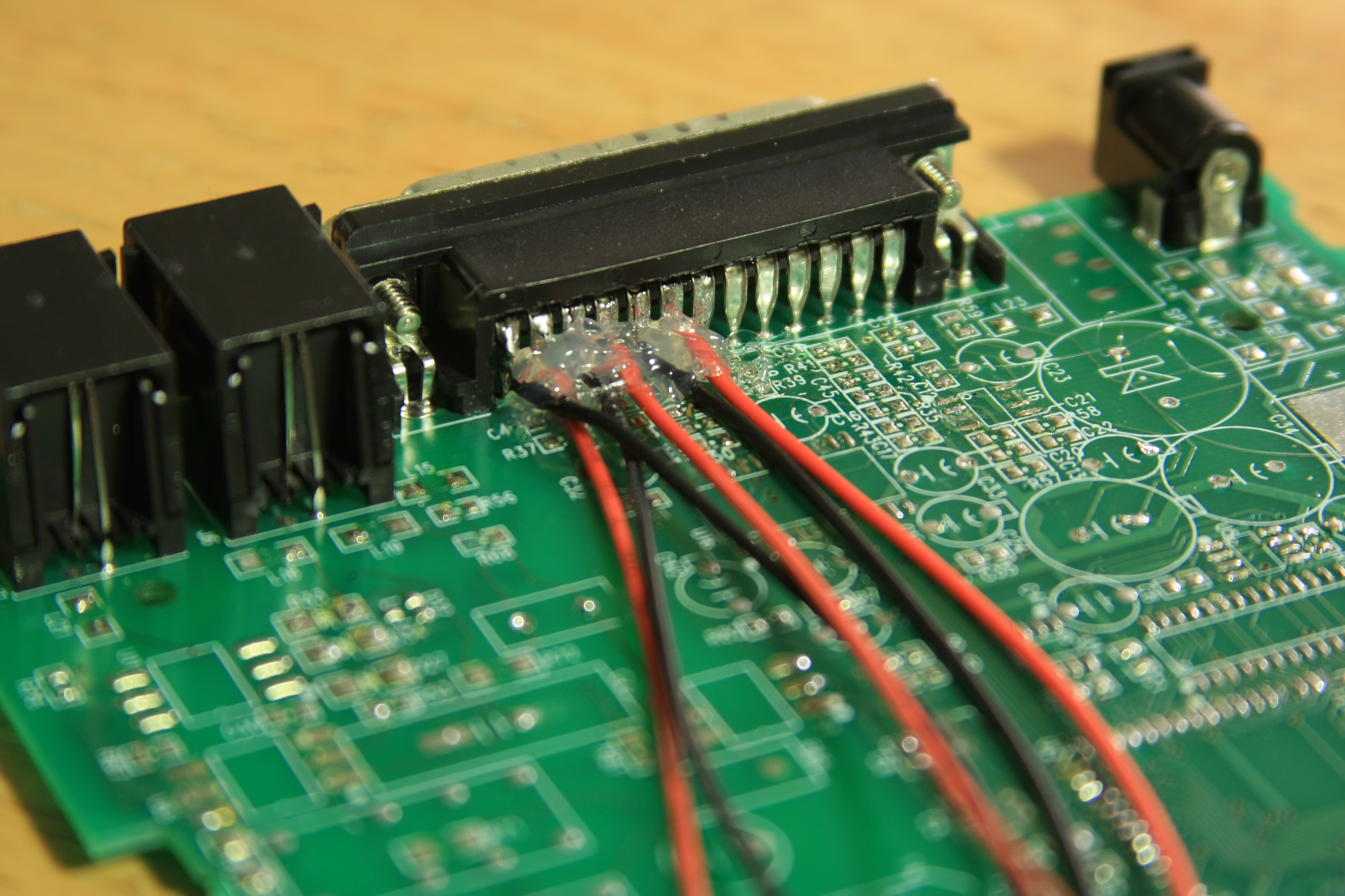
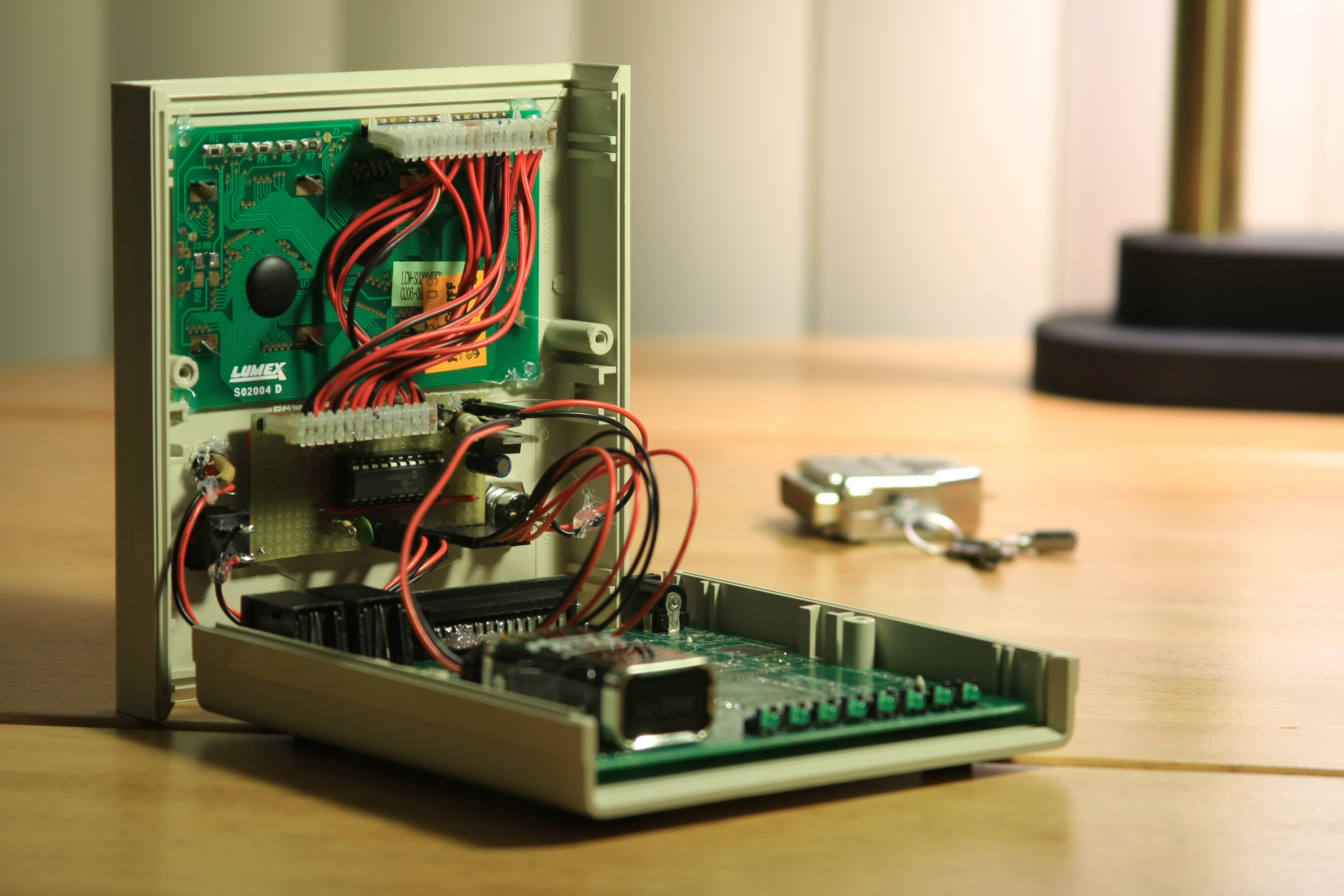
First step was to take the internal board out and unsolder everything that is not needed. In this case, that means to leave only the connectors at the back of the PCB and a row of LEDs that I find quite unpleasant to unsolder (because the plastic rail that holds the LEDs in place melts).
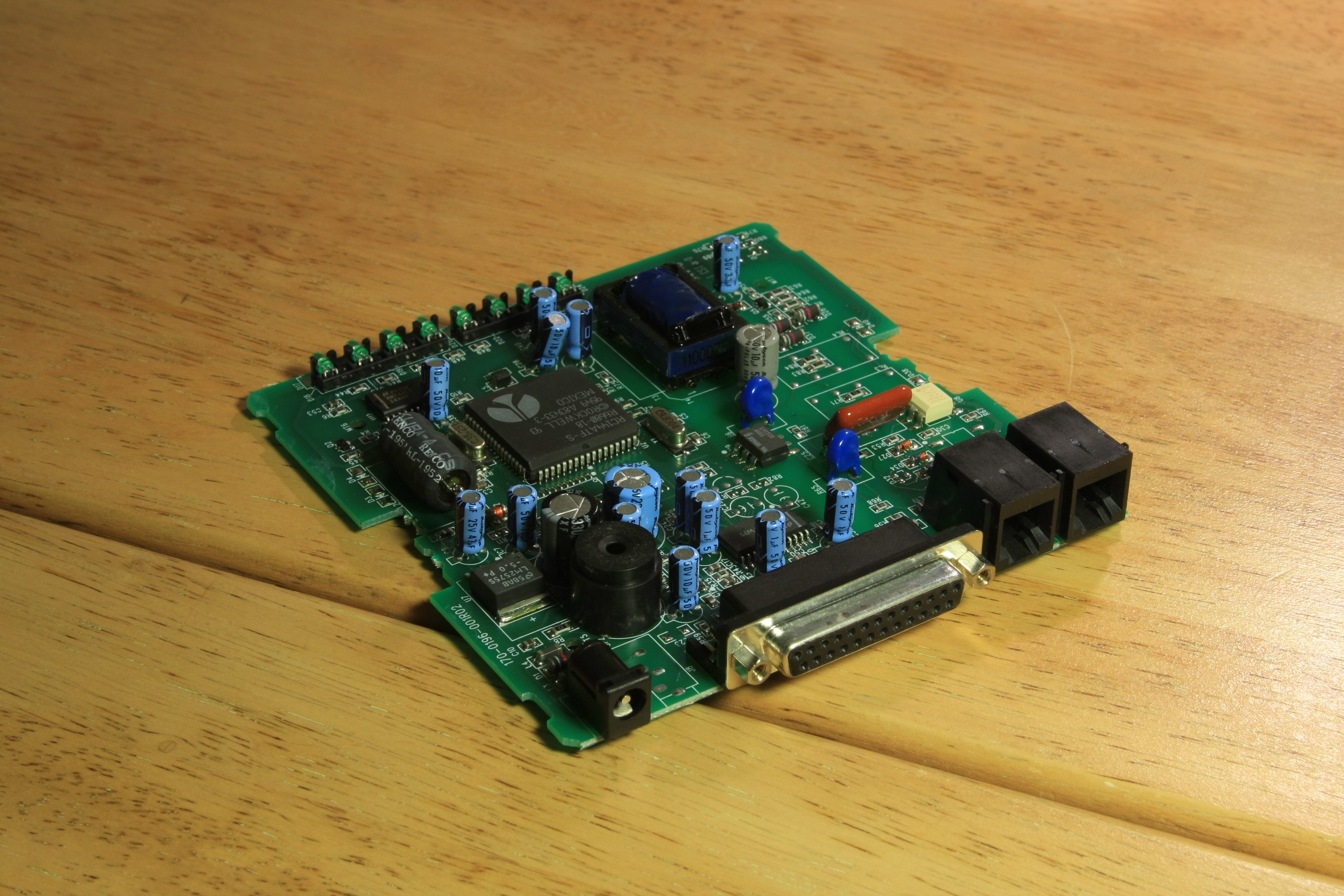
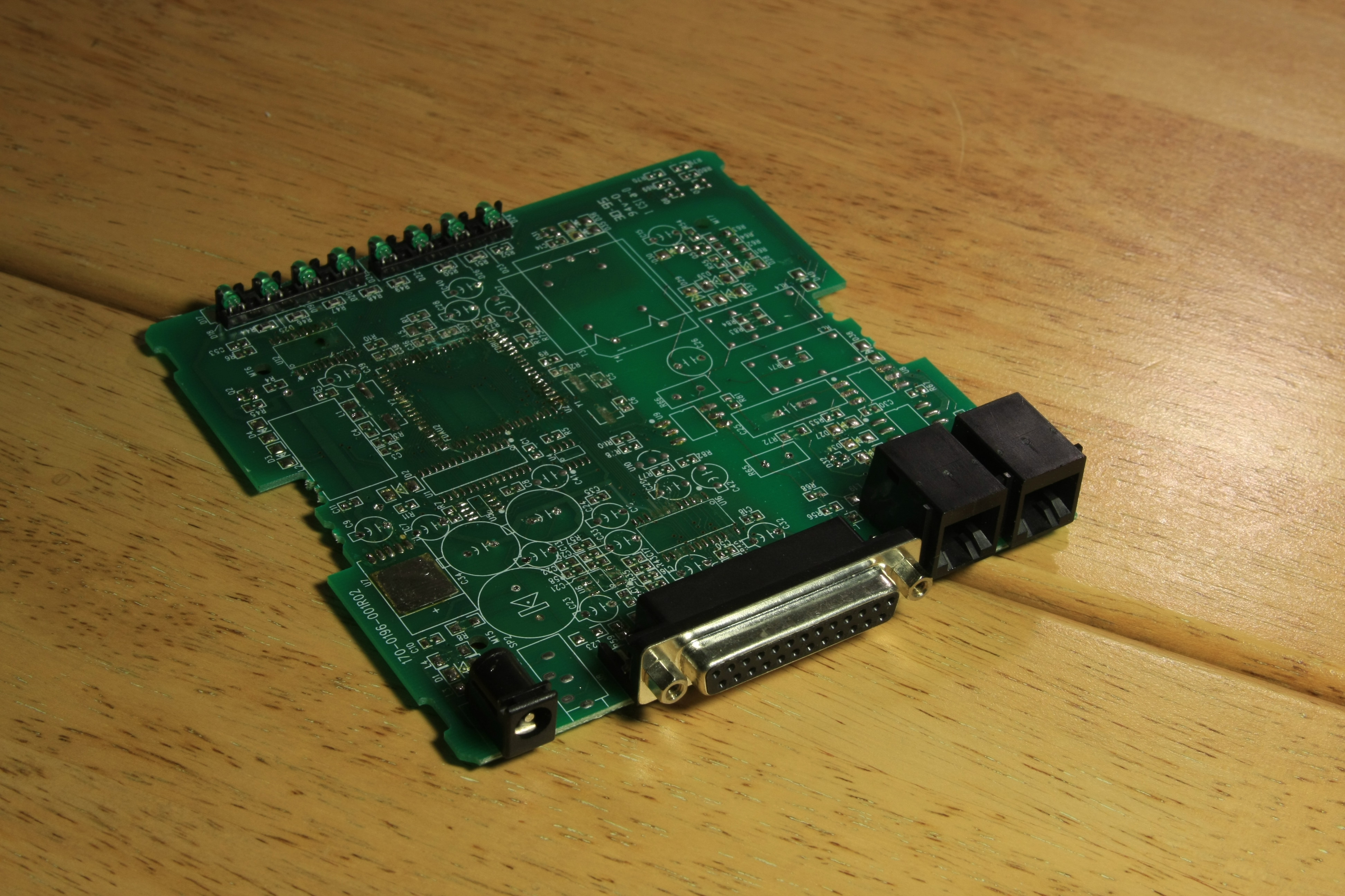
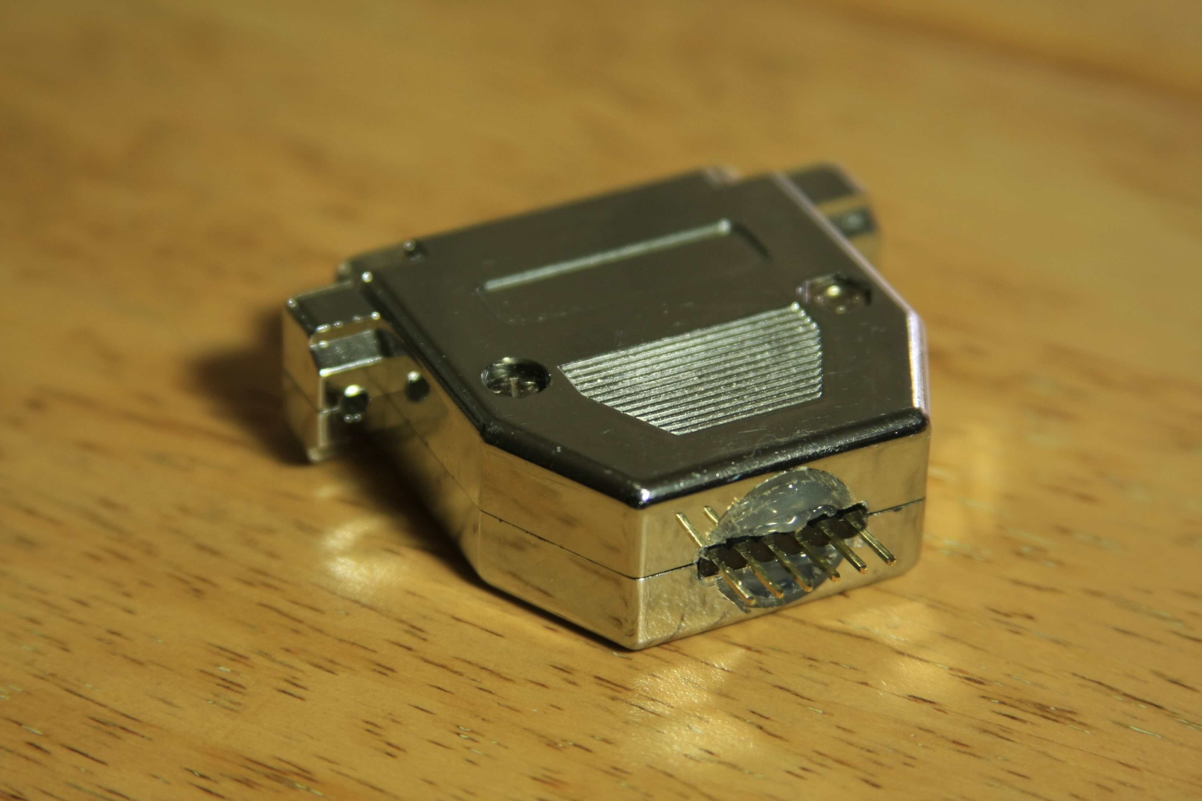
Next came cutting through the traces on the PCB that the parallel port was attached to, and soldering a connector to some of the pins. This connection, along with an external adapter that I already had ready from my Mars Clock project, will let me plug the PICKit 2 programmer directly and reprogram the PIC as it sits inside the box.
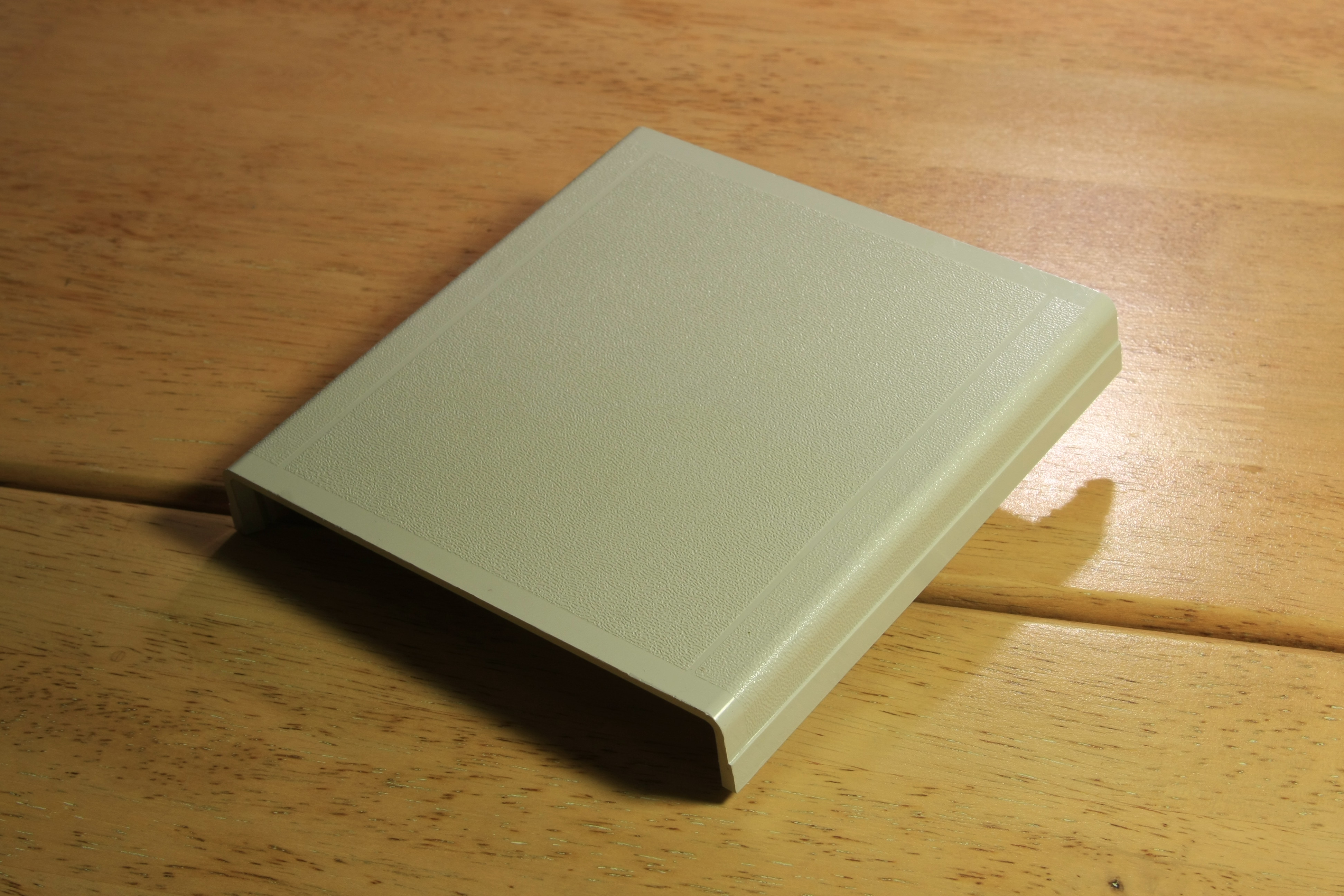
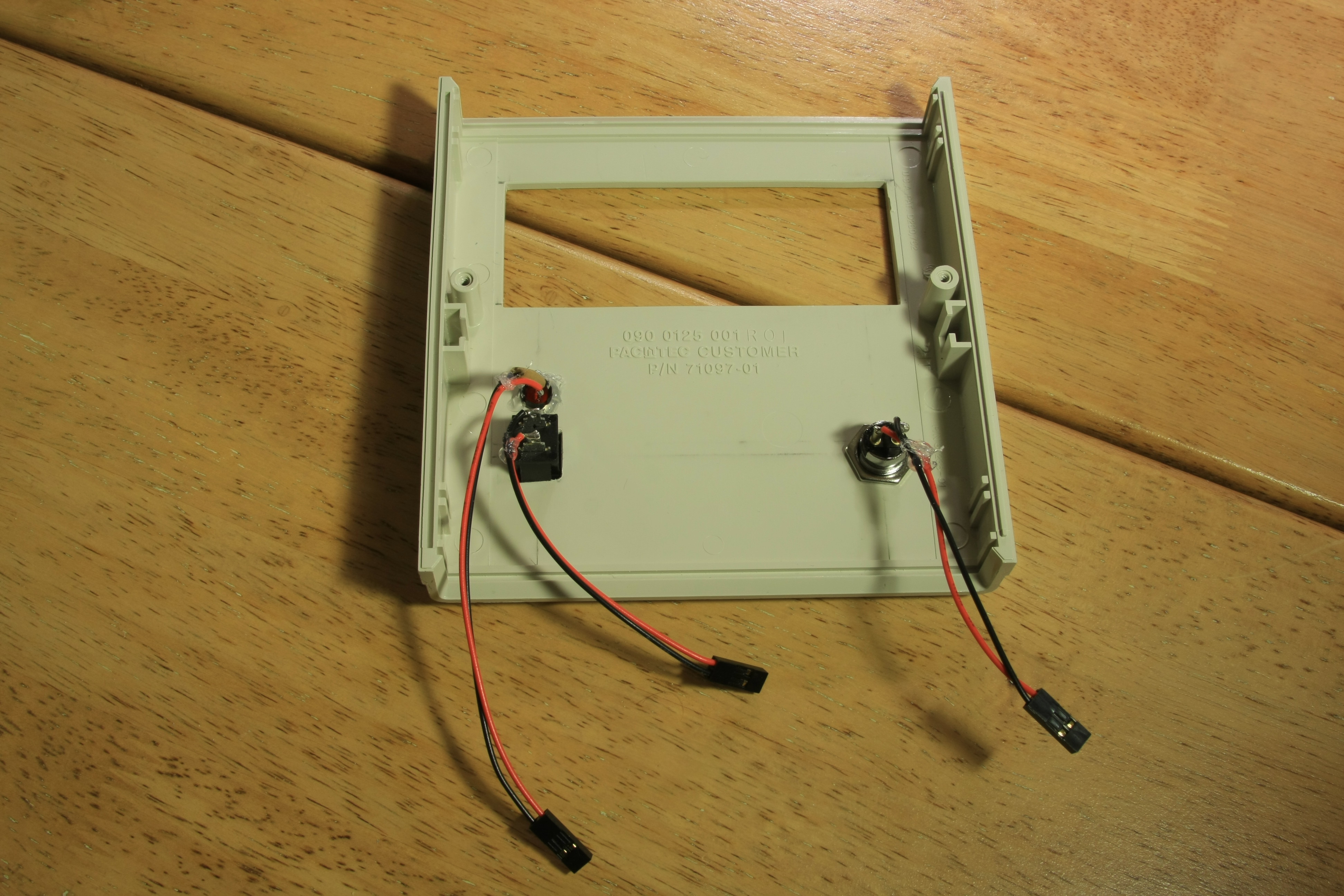
The top plate of the thing formerly known as "a modem" needs some modifications. Here are the "before" and "after" pictures:
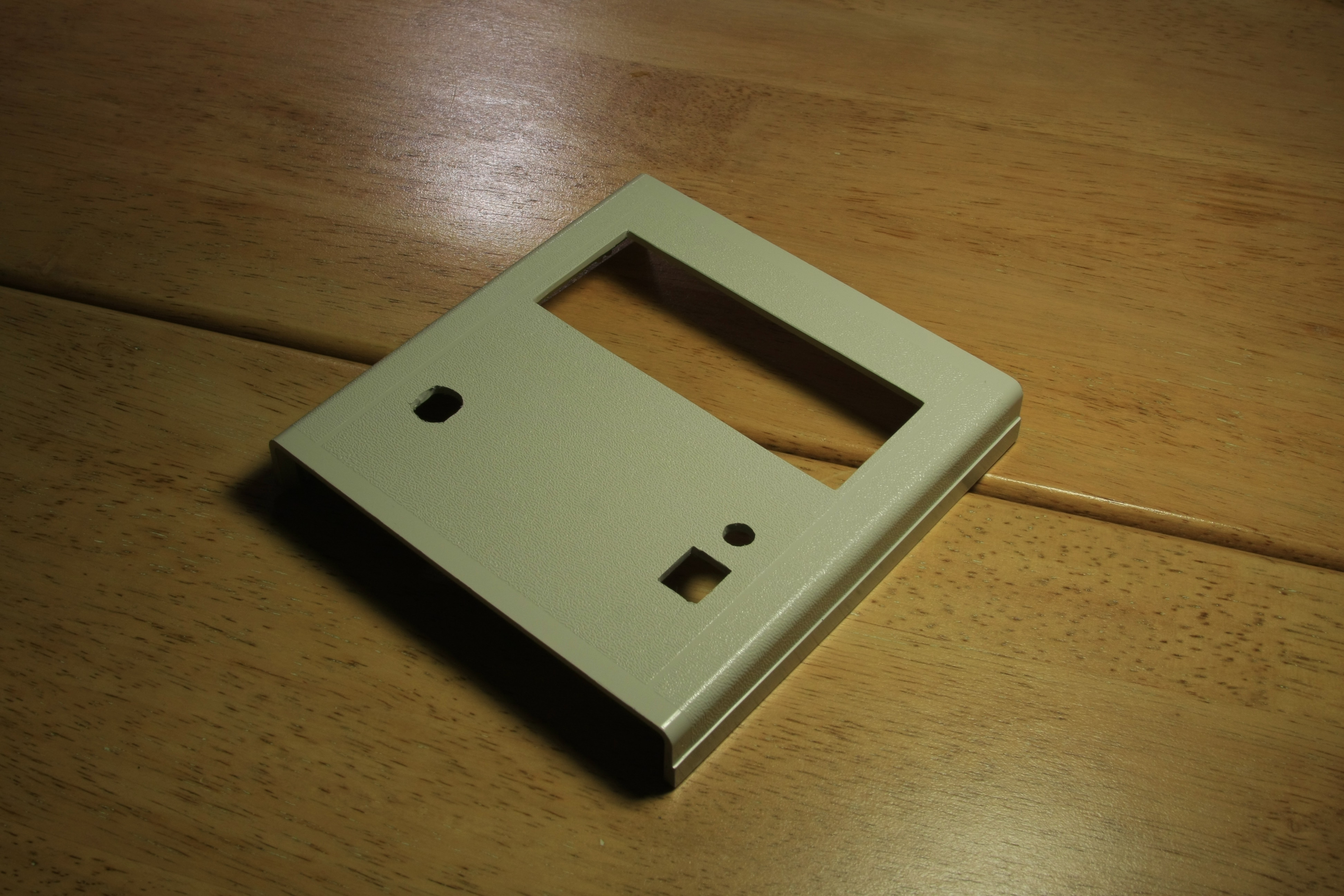
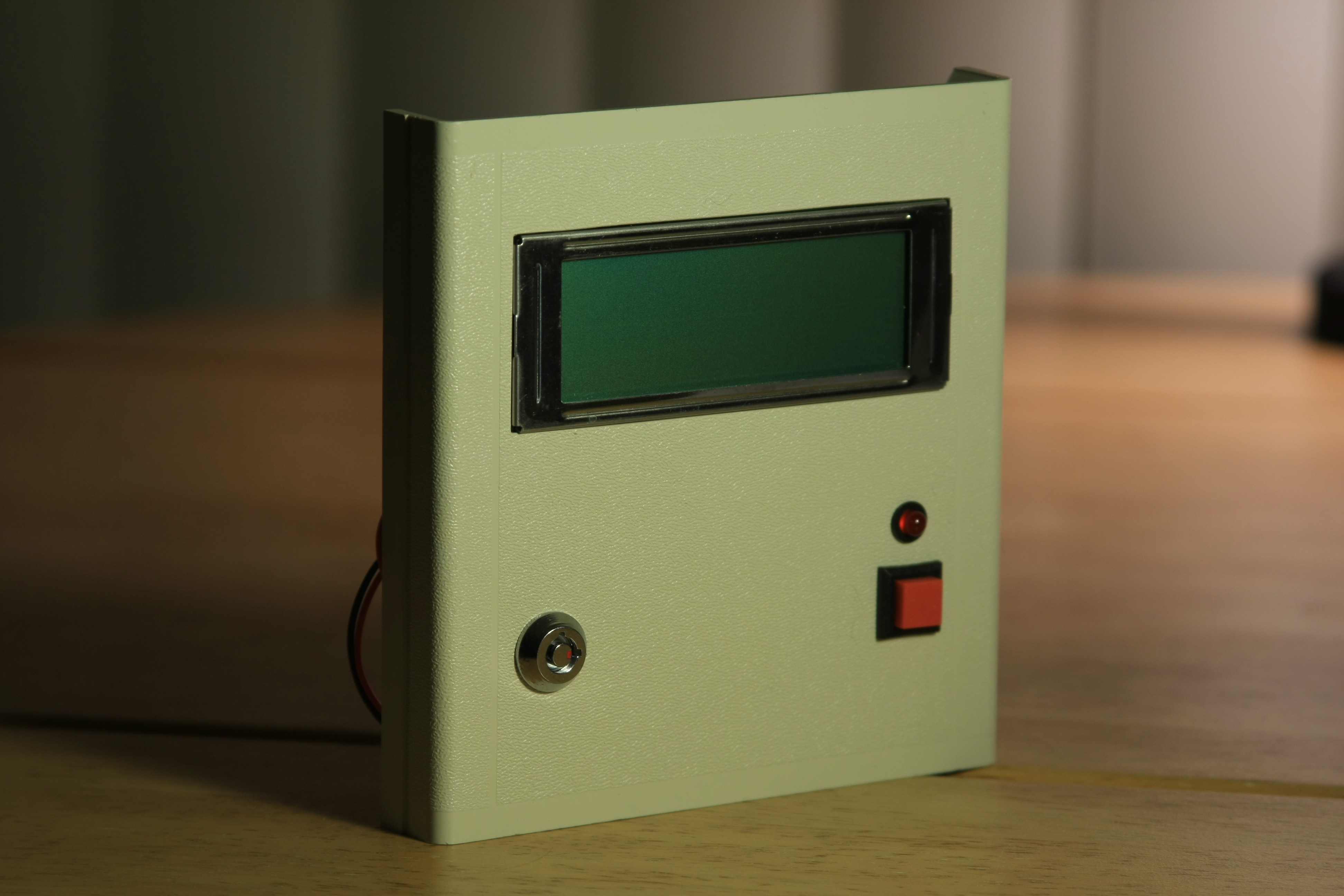
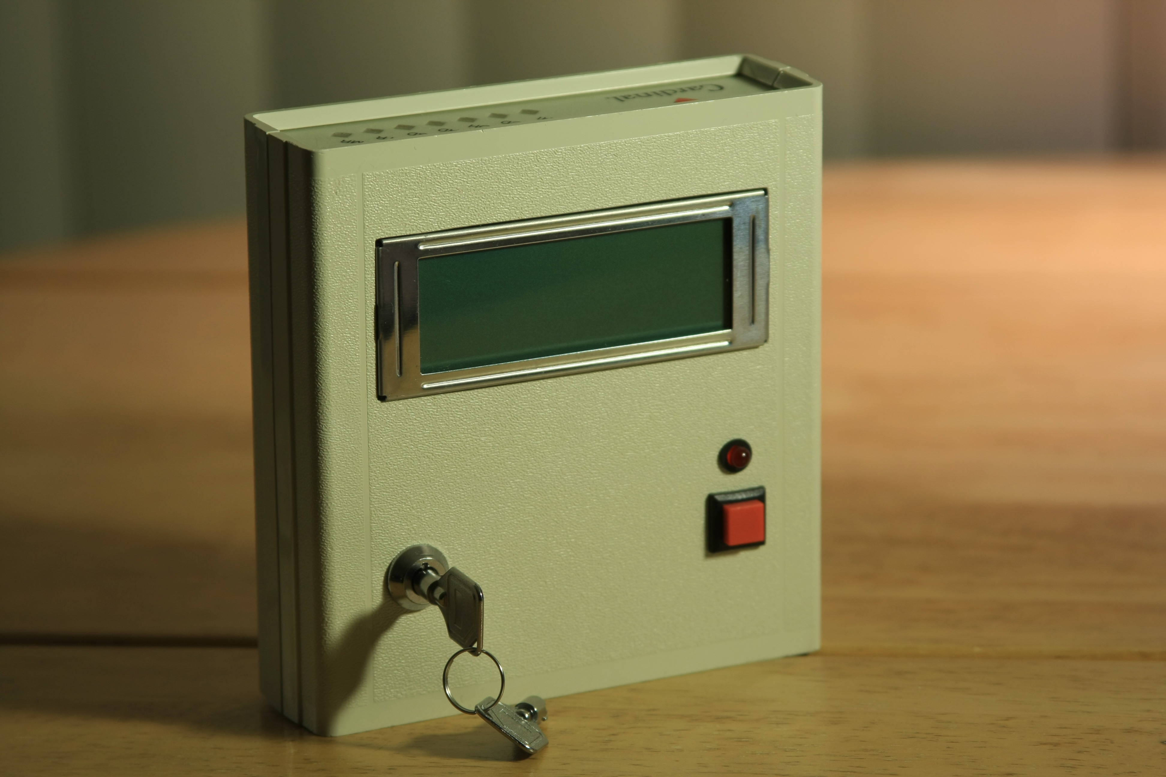
After attaching the power switch, a button, and a LED, the generator's "face" starts to take shape.
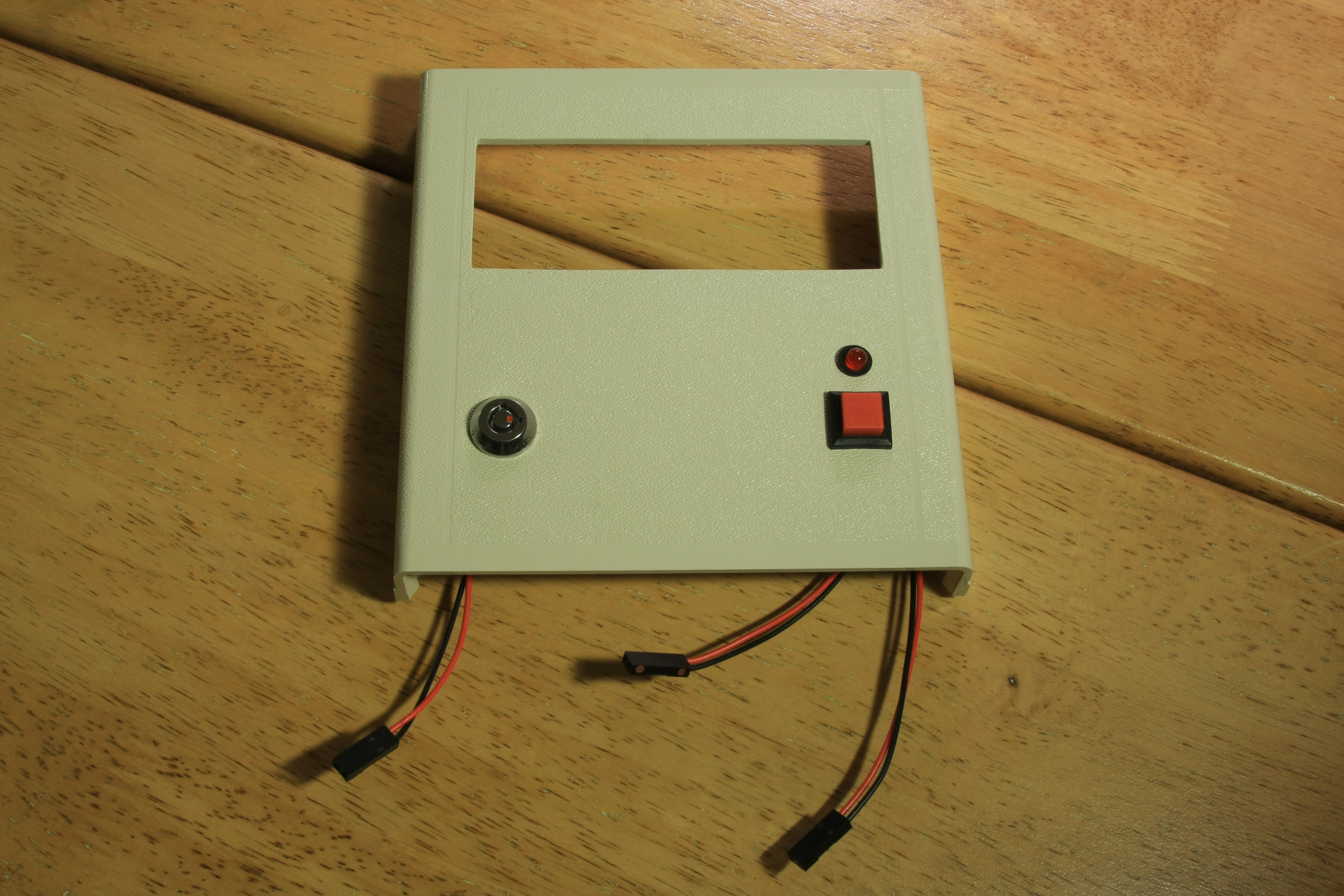
The key metal switch on the left will be used to power-up the device. The button and the LED on the right side will control when new excuse is to be generated and also will handle paging for longer text that doesn't fit on one screen.
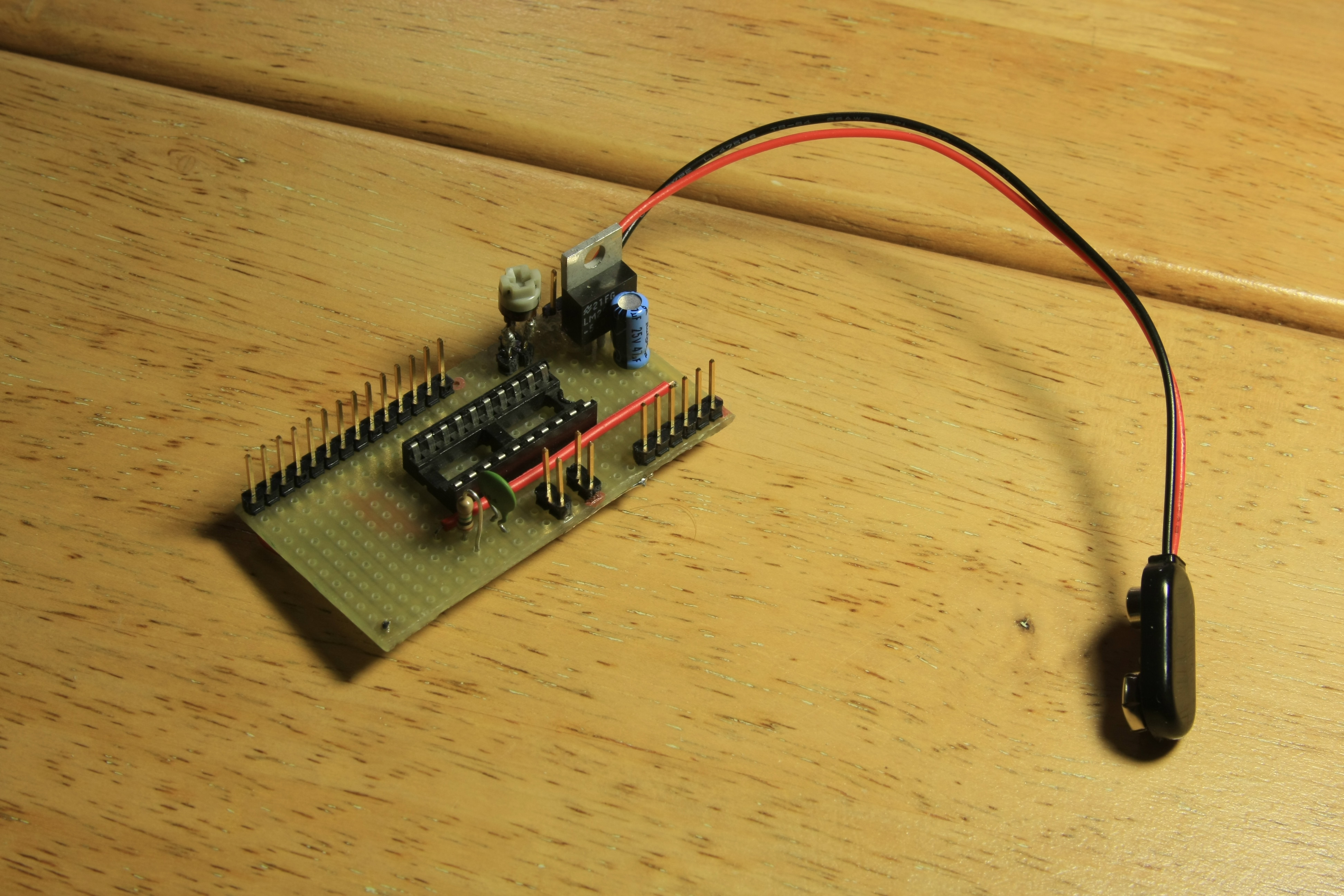
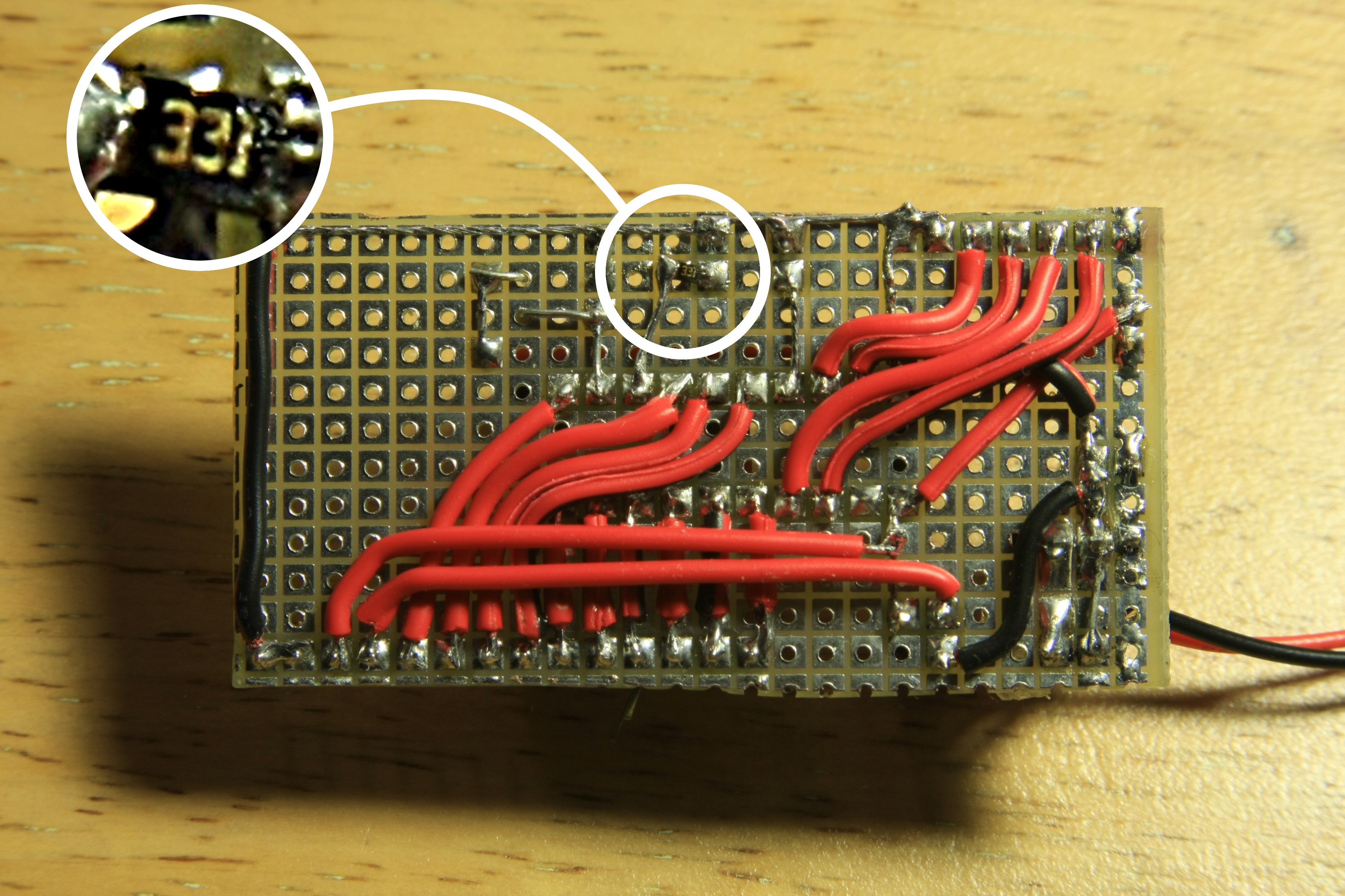
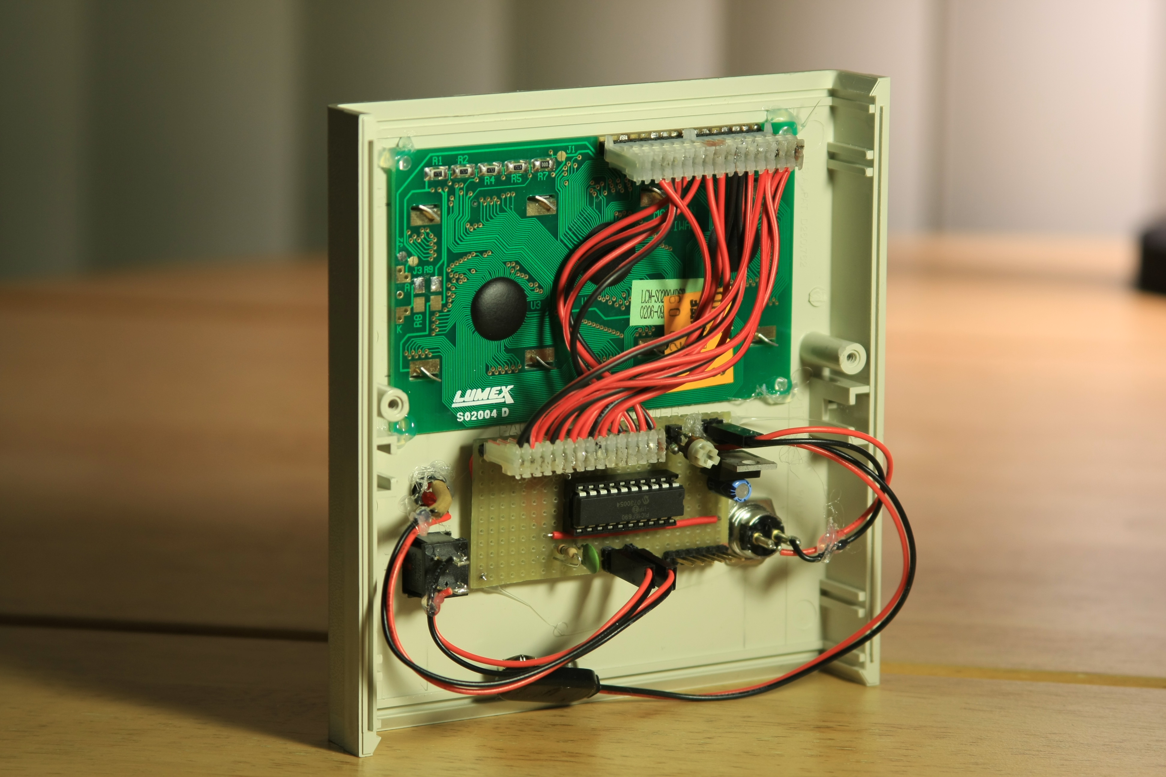
The PIC board contains the power supply, the LCD contrast trimmer potentiometer, the random-generator circuit, and the headers for connecting the controls and ports. It also contains the 330 Ohm current limiting resistor for the LED - this was the first time I used a surface mount component in a project (circled on picture on the right). It came from the modem PCB and did a good job, because I didn't have appropriate replacement on hand.
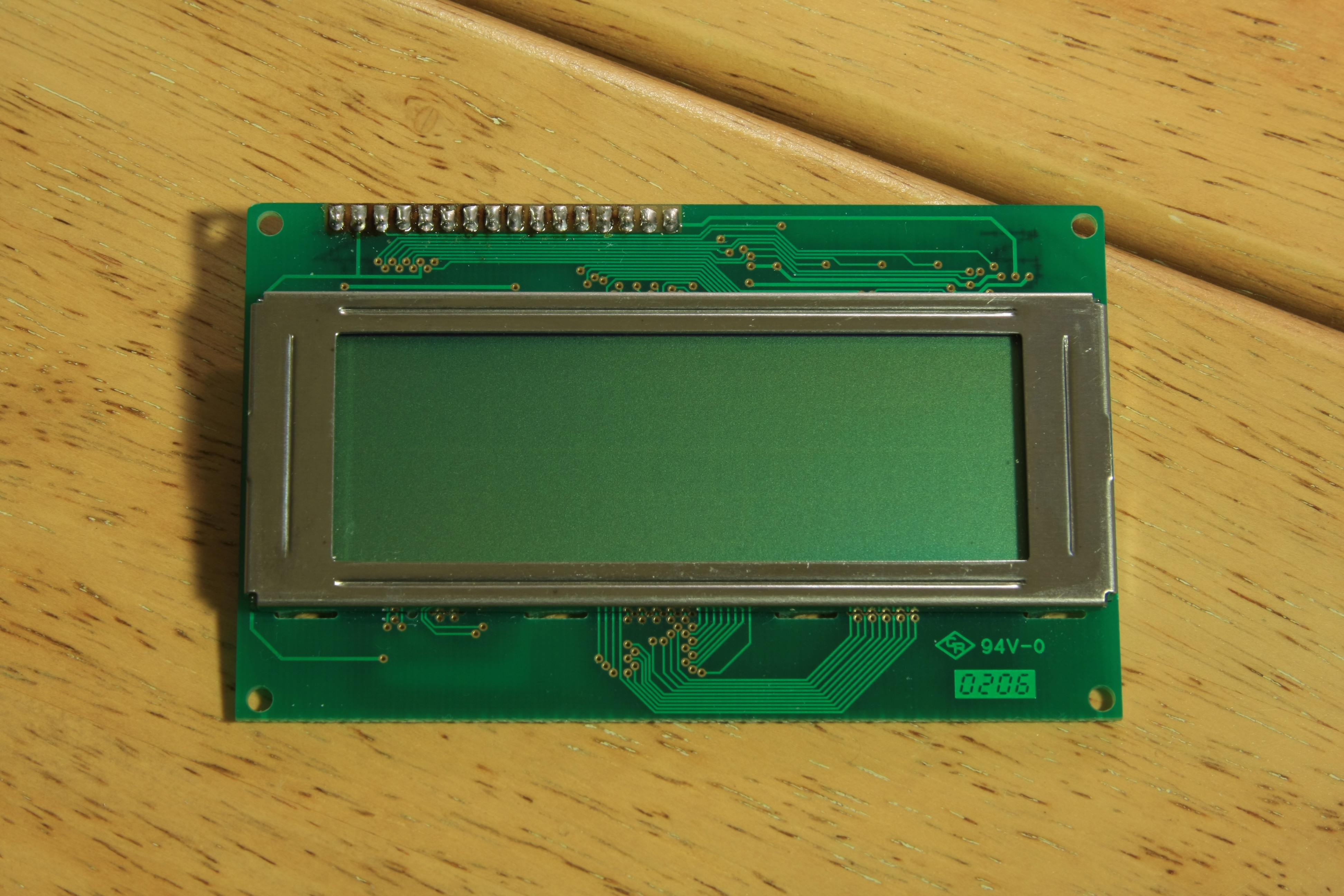
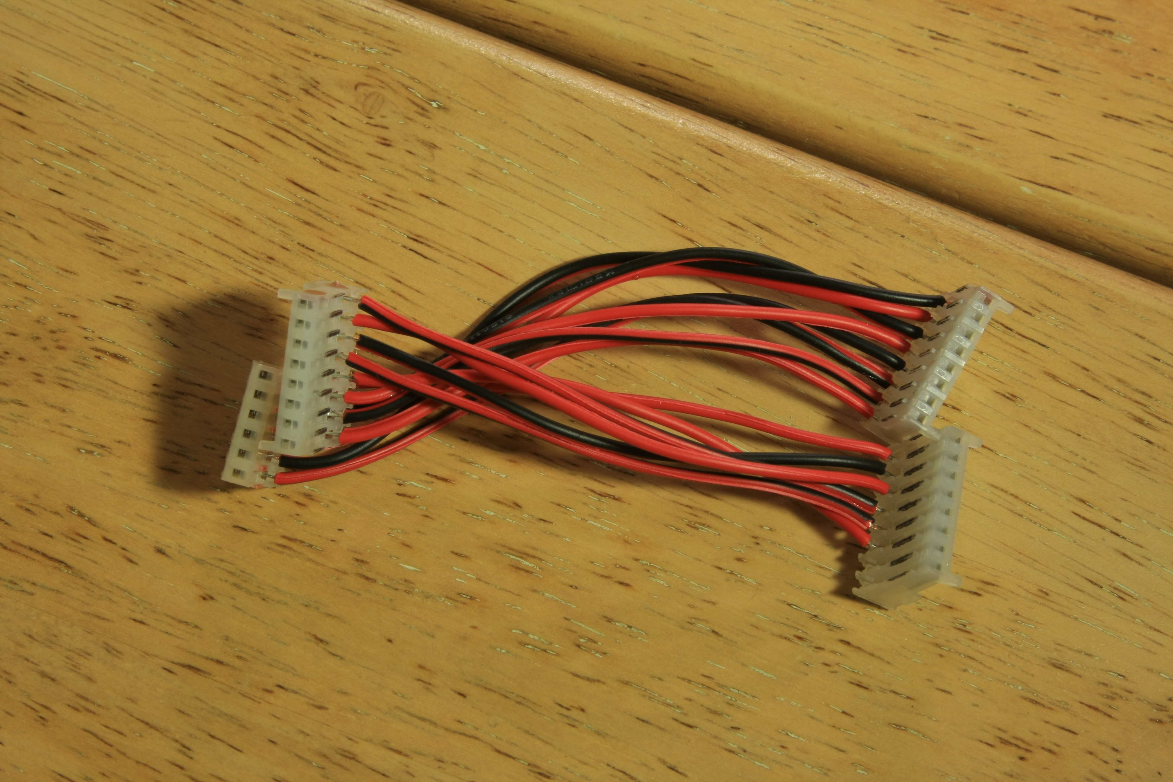
The last part is the LCD and a wicked connecting cable to plug the LCD in the microcontroller board. I found that instead of doing all that complex wire layout and routing on the board, for such handmade projects it is often better to have all the wire crossings done in the cable. It makes for a simple and clean board layout.
Special thanks to whoever invented the glue gun! Attaching everything in place takes just seconds:
All that's left is to plug in the power supply and programming port cable, then close the box.
| Main | Schematics & Code | Construction | Customize It! | Try It! | Other Projects | |||||||||
 | ||||||||||||||