|
|
|
|
|
|
We have a nice big van that we often use for long road and camping trips.
For getting extra light and saving power when camping, I decided to replace some of the interior lights of the van with LEDs.
Normally, I would use a current-limiting resistor, but because of the variabile voltage in the car (see the "Why a current-limiting resistor would not work" section below) this was not an option.
Instead, I went with the following approach:
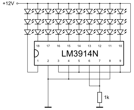
The LM3914 is an adjustable current LED driver.
It is generally used for building bar LED displays, but here it is wired to simply provide constant current to all LEDs.
The 1k "current programming" resistor provides reference for the current that is going to be drawn through each of the LED segments.
Check the LM3914 datasheet on how to calculate the resistor value for different LED currents.
1k corresponds to a current of approximately 15 mA - chosen because this is the nominal current for the LEDs I'm using.
If you have any questions or comments, please do not hesitate to contact me. My e-mail address is at the bottom of this page.
Why a current-limiting resistor would not work
The easiest way to connect a series of LEDs to the 12V power in the car would seem to be with a limiting resistor:
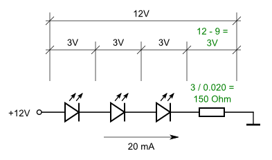
Calculating the limiting resistor is simple.
Let's assume a typical 3V voltage drop for a single white LED and 20 mA rated current. The three LEDs in series will have a total of 9V drop, the remaining 12V - 9V = 3V drop will have to be on the resistor. At 20 mA, the resistance comes to 12V / 120mA = 12 / 0.020 = 150 Ohm.
If it was just that simple...
The problem is that in a car (or at least - in my car) the voltage varies.
When the engine is not running, I was getting around 12V, but with the engine on the voltage was jumping to a bit over 14V.
Let's do the math.
The voltage on the LEDs is more or less constant - let's keep this at 3V.
The voltage drop on the resistor would then be 14V - 9V = 5V.
The 150 Ohm resistor would then produce a current of around 5V / 150 Ohm = 33.3 mA.
This may not immediately fry the LEDs, but it will at least reduce their lifetime significantly.
Of course, one can calculate the resistor for this higher voltage, but then the current (and therefore brightness) will drop once the engine is off. Not nice.
Disclaimer
I do not assume responsibility for anything that can go wrong if you decide to do this project.
Make sure you work safely, do not short-circuit anything, check if heat from the LEDs and the driver IC can dissipate without setting anything on fire, etc.
In other words, if you blow your car to smithereens, don't blame me.
|
|
|
|
|
|
|